P&ID Drawings stand for Piping and Instrumentation Diagram. These are technical documents created by process engineers to describe the piping systems and related components in a process flow. A P&ID provides a detailed graphical representation of the actual process system, including piping, equipment, valves, measurement instruments, and other components within the system. All these elements are represented using various P&ID symbols.
The graphical representation in a P&ID illustrates the functional relationships between piping, instrumentation, and mechanical equipment. A P&ID drawing is one of the most critical documents for any project, playing a vital role in all stages of process development and operation. It is the most widely used technical document, applicable to multiple engineering fields such as Process, Piping, Mechanical, Construction, HVAC, Power Plants, Electrical, and Instrumentation.
1. What are P&IDs used for?
P&IDs (also referred to as PEFS – Process Engineering Flow Scheme) serve multiple purposes as a fundamental technical document:
- Defining and arranging key components of piping and instrumentation systems:
P&IDs provide detailed information on critical components and their layout within the system. - Baseline for operations, control, and shutdowns:
P&IDs form the foundation for designing operating procedures, system control, and planning safe shutdowns. - Supporting maintenance and modifications:
P&IDs offer the framework for conducting maintenance and making adjustments, ensuring efficiency and accuracy in repairs and system upgrades. - Meeting safety and regulatory requirements:
These documents outline the safety standards and regulatory requirements to be followed within the facility, ensuring compliance with legal and technical standards. - Guiding operations and startup:
P&IDs serve as the primary reference for system startup and operation, providing essential details and data needed to initiate processes. - Establishing operational standards:
Operational procedures and standards are developed based on P&IDs, ensuring consistent and efficient facility operations. - Training documentation:
P&IDs are foundational materials for training, helping operators, field engineers, and maintenance teams understand the interconnections between piping, instrumentation, and equipment. - Planning design and construction:
P&IDs support the systematic planning of design and construction sequences for facilities. - Troubleshooting and failure analysis:
These documents serve as a reference for analyzing mechanical and chemical steps, helping identify root causes when issues arise. - Project cost estimation:
P&IDs provide the initial information needed for accurate project cost estimation. - Assisting in critical reviews:
P&IDs are essential for evaluations like HAZOP, model reviews, and process safety management. - Serving as a common language for plant operations:
Finally, P&IDs act as a universal language, enabling all stakeholders to discuss and coordinate plant operations effectively.
P&IDs are indispensable documents throughout every stage of engineering design, construction, operation, and maintenance of technical systems. Their versatility and detailed representation make them a cornerstone in the successful execution of engineering projects.
2. What does a P&ID typically include?
There is no universally mandated standard or regulation specifying the exact contents of a P&ID. As a result, P&IDs may vary slightly depending on the organization. However, most P&IDs typically include the following components:
- All mechanical equipment labeled with tags and specific names.
- All types of valves, clearly marked and identified.
- Instrumentation details, represented with standardized symbols.
- Pipelines, including pipeline numbers, dimensions, material specifications, and additional details.
- Flow direction of the process fluid.
- Other components, such as drains, vents, special fittings, reducers, sample lines, expansion joints, flexible hoses, and extensions or reductions.
- Interfaces between pipelines and equipment, including defined boundaries and changes in technical standards.
- Fixed startup and flushing lines.
- Cross-references for interconnections.
- Interlocks and control system inputs/outputs.
- Alarm inputs.
- Physical sequence of piping and equipment components.
- Equipment capacity or performance data, sometimes accompanied by brief design information or dimensional details.
- Interfaces with suppliers and contractors, including their scope of work.
- Inputs for computer control systems.
- Seismic classifications.
- Quality levels.
- Details such as operating, standby, or infrequently flowing states of equipment.
- Notes on two-phase flows, special pipe length requirements, etc.
- Pipeline slope requirements and insulation needs.
A P&ID document must ensure accuracy and comprehensiveness to effectively support the design, operation, and maintenance of technical systems.
3. P&ID Symbols
When creating a P&ID diagram, process engineers use a variety of P&ID symbols. These symbols are typically outlined at the beginning of the P&ID document set. For consistency, the same symbols are generally maintained by the designer. Users should familiarize themselves with these symbols to accurately read and interpret P&ID diagrams.
3.1. Instrumentation and Tools Symbols in P&ID
A system of letter-based symbols is used to identify instruments and their associated functions. This standardized notation provides clarity and ensures a uniform understanding of the P&ID elements.
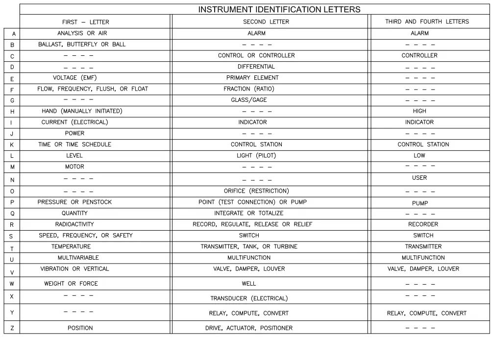
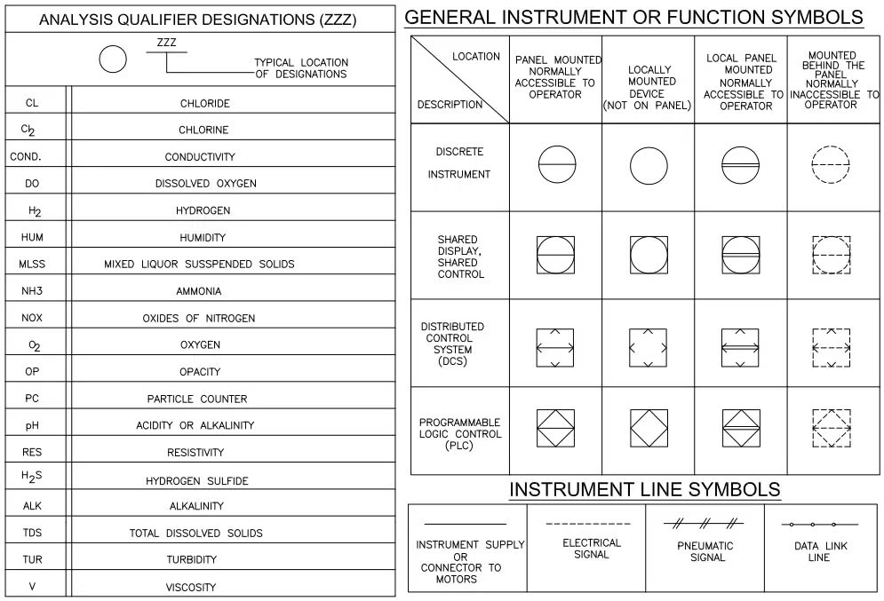
3.2. P&ID Symbols – Miscellaneous Equipment
P&ID diagrams include symbols for auxiliary equipment to represent components that support primary processes. These symbols ensure detailed visualization of all essential elements in the system.
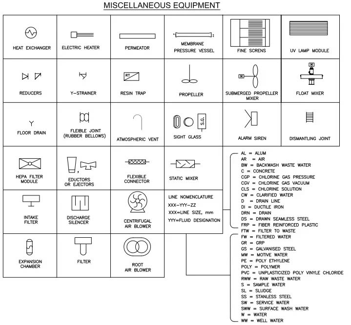
3.3. Valve symbols in Piping and Instrumentation Diagrams
Valves are critical components in any system and are represented in P&IDs with distinct symbols. These symbols indicate the type of valve (e.g., gate, globe, check) and their operational details, such as manual or automatic actuation.
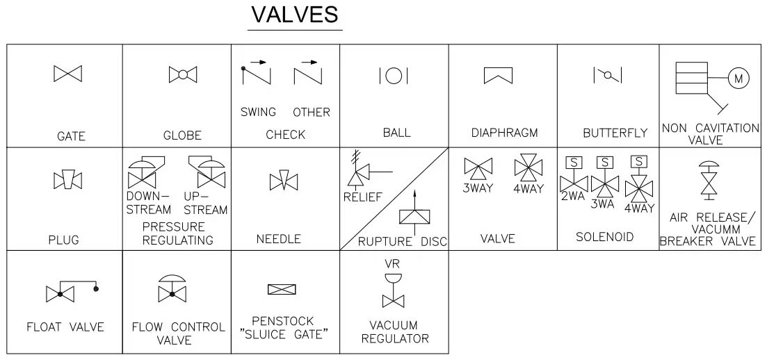
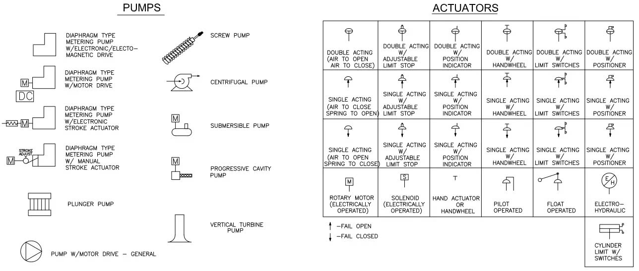
3.4. P&ID symbols for Pumps and Actuators
Pumps and actuators are key to fluid movement and system automation. P&ID symbols for these components reflect their specific types (e.g., centrifugal, positive displacement) and operational roles within the process.
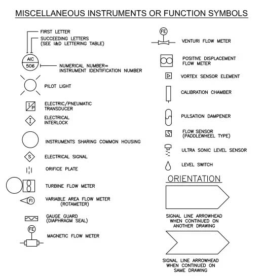
3.5. P&ID symbols for Instruments and Auxiliary Functions
Instrumentation symbols in P&IDs cover measuring devices and auxiliary functions, such as temperature, pressure, flow, and level. These symbols use standardized codes to provide a quick reference to their purpose and operation.
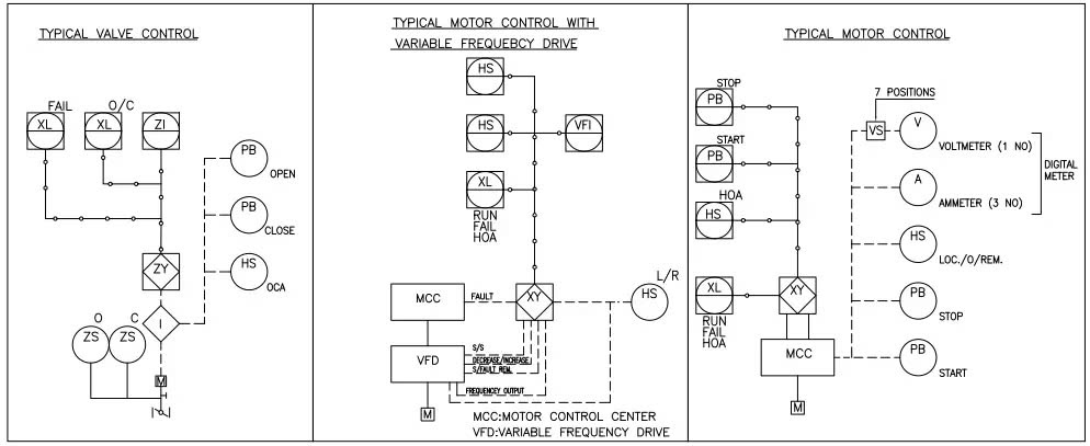
3.6. P&ID symbols for Control Loops
Control loops in P&IDs represent the interaction between sensors, controllers, and actuators. These loops can include various configurations, such as open-loop, closed-loop, and cascaded systems, with their respective symbols indicating the type and complexity of control.
4. Guide to Reading a P&ID Drawings
To read or analyze a P&ID effectively, follow these steps:
1. Familiarize yourself with P&ID Symbols
Start by understanding the basic symbols presented in the diagram, including:
- Mechanical Equipment: pumps, filters, boilers, etc.
- Valves: manual valves, control valves, etc.
- Instruments and Controllers: pressure gauges, flow meters, transmitters, etc.
- Piping: lines for process flow, pipe sizes, material specifications, and directional flow arrows.
2. Identify the process flow
- Trace the direction of the flow by following the arrows on the piping.
- Observe how fluids move through equipment, valves, and connections to understand the operational process.
3. Analyze the example diagram
Take a specific section of a P&ID, such as the one illustrating the suction and discharge lines of Pump P-1519, and break it down:
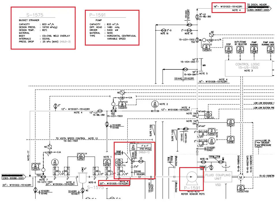
Inlet Piping: The inlet pipeline originates from a different P&ID diagram and connects to the bag filter S-1575.
Piping Details: Information about the pipeline number, pipe size, material specifications, etc., is clearly provided.
Outlet Piping: After leaving the filter’s outlet, the pipeline number changes, and a Pressure Safety Valve (PSV) is installed before entering the reducer at the pump’s suction side.
Material Changes: The piping material specifications change after the reducer and connect to the suction flange of the pump.
Discharge Piping: Similarly, the pump’s discharge flange is connected to the discharge line, with pipeline numbers, sizes, and material specifications (PMS) clearly indicated.
4. Extract Relevant Data
- Use the diagram to extract key data for your purposes, such as material requirements, flow direction, or control elements.
- By applying the same methodology to other sections of the P&ID, you can gain a comprehensive understanding of the system design and process.
This step-by-step approach will help you efficiently interpret and utilize P&ID diagrams for design, operation, or maintenance tasks.
Reference information: https://whatispiping.com/piping-and-instrumentation-diagram-or-pid/
