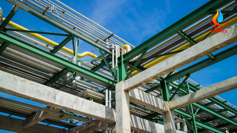
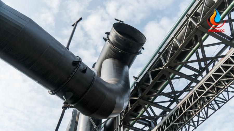
The pipe rack system is a structural framework designed and installed to support multiple pipelines, especially in scenarios where no suitable building or structure is available, typically outside buildings. Pipe racks play a crucial role in organizing pipelines within industrial plants, especially those serving process and utility functions, by connecting all installed equipment located in different parts of the facility.
Beyond pipeline support, pipe racks have various secondary applications, such as carrying electrical cables, signal wires, fire protection systems, lighting, and other auxiliary equipment. Notably, air-cooled heat exchangers or fin-fan units are often mounted on pipe racks to minimize space requirements within the plant. With their flexible structure and multi-functional capabilities, pipe racks optimize space usage and enhance the operational efficiency of industrial plants.
1. What is a Pipe Rack?
A pipe rack is a specially engineered structural system designed to support and secure multiple pipelines within an industrial piping system. According to standards from the American Petroleum Institute (API) and the American Society of Mechanical Engineers (ASME), pipe racks not only ensure system stability but also maintain safety, reduce stress, and mitigate mechanical impacts on pipelines during operation.
1.1. Types of Pipe Racks
By Material:
- Carbon steel pipe racks: Commonly used for their high durability, load-bearing capacity, and cost-effectiveness.
- Stainless steel pipe racks: Suitable for corrosive environments such as chemical plants or marine settings.
- Composite pipe racks: Lightweight, corrosion-resistant, and typically used in systems requiring low weight.
By Structure:
- Simple racks: Comprise fixed supports or hangers for small pipelines.
- Complex racks: Include multi-tier systems or combined frameworks, often used in large-scale plants.
- Portal frame racks: Designed in H or T-frame configurations, widely used in refineries and chemical plants.
By Function:
- Fixed supports: Keep pipelines in a stationary position, managing vertical and horizontal loads.
- Movable supports: Allow pipelines to shift to accommodate thermal expansion or vibrations.
- Suspended supports: Installed for pipelines positioned on ceilings or elevated structures.
1.2. Working Principles of Pipe Racks
Pipe racks operate based on structural and mechanical principles to provide optimal support and stability for piping systems.
Load Distribution:
The primary role of pipe racks is to distribute loads effectively. The weight of pipelines and their contents is transferred to horizontal beams, which then distribute the load uniformly to the rack’s vertical supports. Additionally, bracing components are integrated to mitigate tensile forces or vibrations, especially in conditions subject to high winds, seismic activity, or operational vibrations.
Motion Control:
Pipe racks manage system movement effectively. Pipe clamps and hangers ensure pipelines remain in their designed positions. In movable supports, these components allow flexible pipe movement to adapt to thermal or pressure-induced changes, preventing system deformation.
Integration of Auxiliary Systems:
Pipe racks also support auxiliary systems such as electrical wiring, gas conduits, or fire protection equipment. Their load-bearing capacity and systematic layout maximize installation space, ensuring synchronized operation and high efficiency.
By adhering to standard design principles, pipe racks are not just structural elements but are critical factors determining the safety and performance of entire industrial systems.

1.3. Key components of a Pipe Rack System
Columns: These are the primary load-bearing elements of the pipe rack, anchored to the ground or connected to the foundation.
Beams: Horizontal members that support the pipes, typically mounted on the columns.
Bracings: Reinforce the stability of the entire structure, reducing vibrations and resisting external forces.
Pipe Clamps: Secure the pipes in place, minimizing friction and preventing unwanted movement.
Hangers: Used to suspend smaller pipelines or auxiliary systems such as electrical cables and gas conduits.
2. Essential data for Pipe Rack Design
Designing a pipe rack system requires critical documentation to ensure accuracy and efficiency during the design and construction process.
These include:
- P&ID (Piping and Instrumentation Diagrams): Illustrating the pipeline and equipment layout.
- Flow Diagrams: Detailing the flow of materials through the system.
- Plot Plan: Providing an overall layout of the facility.
- Layout Specifications: Technical requirements for arrangement.
- Client Requirements: Specific needs or preferences outlined by the client.
- Construction Material Details: Specifications for materials to be used.
- Fire Protection Requirements: Standards for fire safety measures.
- Adjacent Equipment Information: Details about surrounding equipment to account for space and integration.
The design process begins with determining the width, spacing, and height of the structural components. Once these parameters are established, a piping route diagram is prepared to finalize the arrangement and support system.

3. Criteria for Pipe Rack Design
Shape of the Pipe Rack
Pipe racks can be designed in various shapes such as L, T, U, H, and Z. The choice of shape depends on the available space at the construction site and the project requirements.
Space Allocation for Future Modifications
The total width of the pipe rack must include spare space for future expansions or modifications:
- For racks up to 16 meters wide: Allocate 25% spare space.
- For racks over 16 meters wide: Allocate 10% spare space.
This percentage is usually based on client requirements.
Width of the Pipe Rack
- Single-bay pipe racks are commonly designed with widths of 6m, 8m, or 10m.
- Double-bay racks typically measure 12m, 16m, or 20m wide, with up to four tiers.
- The spacing between portals is generally 6m but may extend to 8m to accommodate larger pumps or equipment beneath the rack.
Clearance Height Under the Pipe Rack
- In-Plant Units: The minimum clearance height under the rack should be 4m for both longitudinal and lateral directions.
- Offsite Areas: The minimum clearance is 2.2m for both directions.
- Roadways: Clearance height must be at least 7m for main roads and 5m for auxiliary roads.

Load Requirements for the Pipe Rack
The load capacity of the pipe rack is determined by stress analysis to ensure stability and load-bearing efficiency. The following types of loads must be considered:
Dead Load: Includes the weight of pipes, valves, and insulation.
Thermal Load: Arising from pipe expansion due to temperature changes and internal pressure reactions from expansion joints.
Dynamic Load: Caused by vibrations in the pipes and external forces such as wind or seismic activities.
Occasional Load: Includes temporary loads from pipe vibrations, wind, and seismic forces.
Sustained Load: Due to the static pressure of fluids during hydrostatic testing.
These criteria ensure that the pipe rack design meets the spatial, load-bearing, and safety requirements, providing a reliable and efficient system throughout its operational lifecycle.
