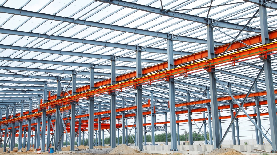
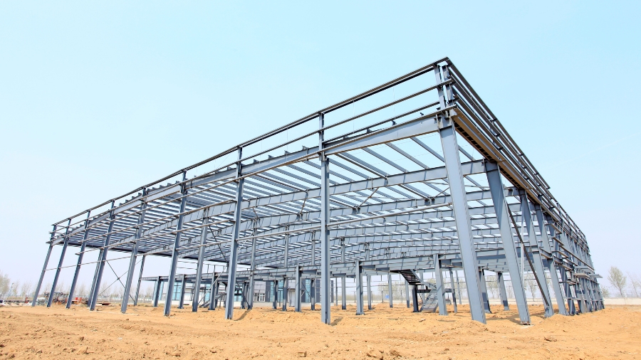
Steel structures are one of the most popular construction solutions in modern engineering due to their superior strength, load-bearing capacity, and high flexibility. The steel structure design process requires a combination of scientific techniques and practical experience to ensure safety, efficiency, and cost optimization for the project.
From determining fundamental factors such as loads, materials, to calculating and analyzing the detailed components of the structure, this process involves many crucial steps, each contributing to the creation of a strong and durable building.
In this article, we will explore the specific steps in the steel structure design process, from planning and technical verification to the final construction drawings, helping engineers and designers understand the fundamental principles and current standards.
1. Determining the suitability of Steel Structures and Projects
Steel structures represent a superior construction solution, especially for projects requiring high load-bearing capacity and complex designs. These projects often demand frameworks that can withstand significant forces from wind, earthquakes, or the weight of multiple floors, while maintaining durability and long service life.
One of the standout features of steel structures is their flexibility in design and installation. Steel components are precisely manufactured in factories, transported to the construction site, and can be easily assembled or disassembled when necessary. This makes steel structures an ideal choice for projects requiring mobility or future expansion.
Additionally, steel structures are well-suited for large-span constructions where other materials might struggle to meet the demands of strength and stability. For example, in stadiums or industrial warehouses, steel frameworks create wide, open spaces without the need for numerous intermediate columns, optimizing functional use.
Typical applications of steel structures include:
- Stadiums and sports centers: Designed for large spans and excellent load-bearing capacity.
- Bridges: Especially suspension or beam bridges.
- Warehouses and factories: Requiring spacious layouts and flexible arrangements.
- Parking lots and high-rise buildings: Demanding robust frameworks and efficient construction.

2. Determining Structural Types and Efficient Layouts
In designing and constructing steel structures, determining the appropriate structural type and layout is one of the most critical steps. This directly influences the project’s functionality and durability. Engineers must rely on the relationship between the overall structural system and its sub-systems while applying technical expertise and real-world operational insights.
Comprehensive Analysis and Planning
First, a comprehensive master design must be developed, identifying the primary and secondary load-bearing points. For example, in an industrial warehouse with a 30-meter span, roof loads must be strategically distributed through main and secondary beams.
Main beams are typically designed using H-shaped steel sections with a sectional height ranging between 1/20 and 1/50 of the span—about 600 mm for a 30-meter span. Secondary beams, often made of I-shaped steel or composite steel, are smaller but still capable of effectively transferring loads to the supporting columns or walls.
Structural Layout for Heavy Loads
In areas subjected to heavy loads, such as roofs in regions with heavy rainfall or strong winds, a slope of 5% to 10% is recommended to ensure proper drainage and reduce stress on the structure. The curvature of the roof must also be carefully calculated to prevent excessive deflection that could exert undue pressure on the underlying framework.
For instance, if a 20-meter roof is subjected to a rain load of 100 kg/m², the total load along the roof will be 2,000 kg. To evenly distribute this force, steel columns with adequate sectional dimensions—such as 400 mm-high composite steel with an 8 mm thickness—must be used to ensure safety under all weather conditions.

Steel Structure Design for High-Rise Buildings
For high-rise buildings, a combination of steel and concrete is essential to enhance stability and minimize oscillations. For instance, reinforced concrete core systems can handle lateral loads (such as wind), while steel beams support vertical loads. Cross-bracing connections between floors help reduce deformation and increase the structural load-bearing capacity.
Comprehensive Mechanical Modeling
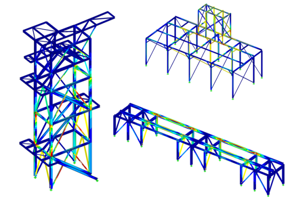
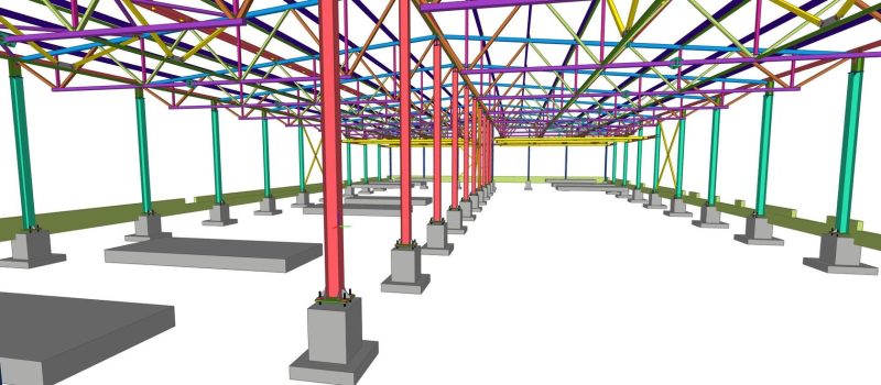
Using structural analysis software such as SAP2000 or Tekla Structures, engineers can simulate the entire load-bearing system. A comprehensive mechanical model demonstrates how forces are distributed across beams, columns, and connection points. For example, if a secondary beam exceeds its allowable load, the system may suggest increasing its dimensions or adding additional connections.

Optimization and Risk Mitigation
Finally, engineers must calculate and propose optimized solutions to minimize risks during construction and operation. For instance, in industrial facilities near coastal areas, corrosion-resistant steel or special protective coatings should be used to extend the lifespan of the structure.
By combining scientific analysis with practical experience, determining and arranging steel structures appropriately ensures both safety and economic efficiency for the project.
3. Estimating the Cross-Sectional Area of Steel Structures
After completing the layout plan, engineers estimate the cross-sectional area of the structure by assuming the shape and dimensions of beams, columns, and bracing elements.
Steel channels or rolled/welded H-beams are commonly used for creating steel beams. The height of the cross-section typically ranges from 1/20 to 1/50 of the beam span. Once the height and width of the cross-section are determined, engineers calculate the thickness of the steel plates in accordance with building standards.
4. Structural Analysis
Structural analysis is a critical step in the design process, enabling the evaluation of load-bearing capacity and ensuring the safety of the structure. Experienced professionals combine scientific analysis methods with practical knowledge to achieve optimal results.
Elastic and Nonlinear Effects
Structural analysis is often based on linear elastic models. However, for greater accuracy, nonlinear effects such as P-Δ (global deformation under significant lateral loads) and P-δ (local deformation of structural components) must be considered. These effects are particularly important for tall structures or long-span systems, where forces can cause substantial deformation.
Key Considerations:
Load Conditions: Each project has unique load requirements.
- For industrial buildings with dynamic crane loads, P-Δ effects must be carefully analyzed.
- For high-rise buildings exposed to wind loads, P-δ effects are critical.
Software Tools:
Advanced programs such as SAP2000 or ETABS enable detailed simulation and calculation of structural deformations. By integrating experimental data with analytical models, engineers can identify potential weak points and adjust designs accordingly.
Compliance with Standards:
Building codes like TCVN, Eurocode, and AISC mandate consideration of nonlinear effects, particularly for structures with high load demands and complex configurations.
In the design of long-span steel bridges, neglecting P-Δ effects can result in excessive deflection under load, potentially leading to premature failure. Comprehensive analysis not only extends the service life of the structure but also reduces long-term repair costs.

5. Technical Specifications Check: A Critical Step in Structural Steel Design
The technical specifications check is an essential phase to ensure the quality and safety of steel structures before construction begins. With years of experience in the field, I can confidently say that thorough checks not only help detect potential errors early but also minimize costs for later corrections.
5.1. Goals of the Technical Specifications Check
- Accuracy Assessment
The check must ensure that parameters such as total shear force, deformation values, and bending moments fall within acceptable limits. This is typically done using simulation software such as SAP2000 or Abaqus, which provides detailed simulations of actual load conditions.
- Adjusting the Design Model
Discrepancies between theoretical calculations and practical outcomes are inevitable, especially in complex projects. For instance, a large industrial warehouse may experience unexpected deformations at areas subjected to dynamic loads, requiring adjustments in beam thickness or the addition of bracing to reduce deflection.
5.2. Important Factors to Check
- Total Shear Force
Assessing the load-bearing capacity of joints and contact points is crucial to ensure that no sliding or local failure occurs. - Deformation
Analyzing the maximum deformation of the structure under various load combinations to ensure it does not exceed international standards such as Eurocode or AISC. - Seismic Resistance
For areas in high seismic zones, it is essential to check the structure’s ability to absorb and dissipate earthquake forces.
6. Design of Other Parts of the Structure
The first step is to determine the materials to be used for each part of the structure. While using a single type of steel may simplify management, combining different types of steel can help save costs and ensure safety.
Currently, many specialized software tools assist in analyzing steel structural sections, making the entire checking process more efficient from start to finish.
Finally, designing the connection points is one of the most critical steps. Before analyzing the structure, these connection points need to be carefully considered. There are three main types of connections: rigid connections, hinge connections, and semi-rigid connections.

7. Preparation of Drawings
There are two types of drawings required during the design preparation phase: Design Drawings and Detailed Drawings. The design drawings are provided by the design unit, while the detailed drawings (construction drawings) are created by the construction unit based on the design drawings.
The design drawings serve as the foundation for creating the detailed drawings. Information such as design basis, load data, material requirements, structural layout, and section choices, along with key points, must be thoroughly prepared. The detailed drawings must be clear and precise enough to support the construction and fabrication processes.
