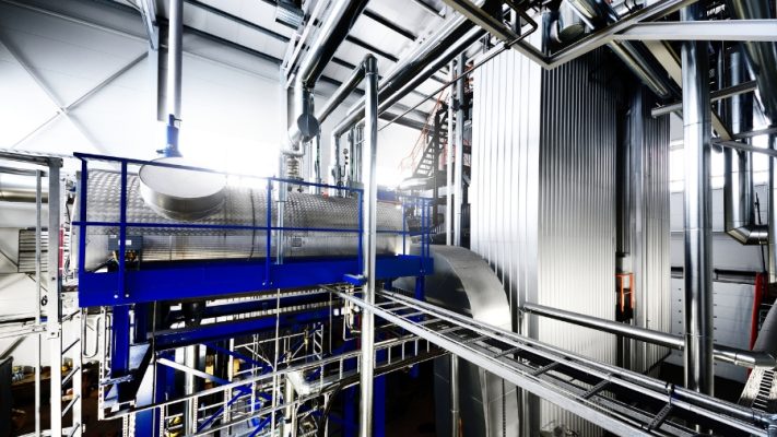
Boiler design is the intricate process of crafting boilers tailored for various applications. The primary function of a boiler is to heat water to generate steam, which serves multiple purposes, including space heating, sterilization, drying, humidification, and power generation. The steam’s temperature and conditions depend on the specific application, necessitating corresponding design adaptations.
1. Gathering boiler design input data
The design process begins with identifying precise technical requirements. Key parameters such as maximum continuous steam output, steam pressure and temperature, load range, and fuel type are critical to selecting equipment that meets practical needs effectively.
1.1. Maximum continuous rating (MCR)
MCR represents the maximum steam output based on the actual demand of connected systems like machinery, heating, or sterilization, plus a contingency margin for sudden load spikes or future expansion. For instance, if 5 tons/hour of steam is required, a 20% buffer increases the design capacity to 6 tons/hour, ensuring operational stability under all scenarios.
1.2. Steam pressure
Steam pressure requirements align directly with the intended application. Low-pressure systems (0.5–10 bar) suit heating or food processes, medium pressure (10–30 bar) is ideal for industrial uses like chemical or paper production, while high-pressure systems (over 30 bar) cater to power generation or heavy-duty operations. For example, a terminal pressure of 8 bar, combined with a pipeline loss of 1.5 bar, necessitates a design pressure of at least 9.5 bar.
1.3. Steam temperature
Steam temperature depends on application needs. Saturated steam suffices for processes not demanding high temperatures, while superheated steam is necessary for turbines, compressors, or high-temperature industrial systems. Superheated steam temperature is determined by adding a safety margin (typically 50–100°C) to the saturated steam temperature.
1.4. Boiler turndown ratio
The turndown ratio reflects the boiler’s ability to operate across varying loads without compromising efficiency. For applications with fluctuating demands, such as batch production, a high turndown ratio (e.g., 4:1 or 10:1) optimizes fuel use and operational efficiency.
1.5. Fuel type
Fuel choice influences both boiler design and operating costs. Coal offers cost advantages for large systems but requires advanced emission controls, while oil and gas are cleaner and easier to operate but come at higher costs. Biomass is an eco-friendly option, particularly for industries generating agricultural by-products.
2. Calculating heat duty for boiler design
Thermal capacity calculations are crucial for ensuring that the boiler meets usage demands reliably. This involves determining the boiler’s heat duty and the burner’s heat input.
2.1. Boiler heat duty
Boiler heat duty quantifies the thermal energy required to produce the desired steam output. The steps include:
- Determining steam enthalpy: Based on the desired steam pressure and temperature, values are extracted from steam tables.
- Calculating total heat demand: Multiply steam enthalpy (kJ/kg) by the required flow rate (kg/h). Results are expressed in MKCal/h, MW, or HP.
For example, producing 6 tons/hour of steam at 10 bar and 184°C, with an enthalpy of 2784 kJ/kg, requires 16,704,000 kJ/h (approximately 4.64 MW).
2.2. Burner heat duty
Burner heat input depends on boiler efficiency and fuel type. It’s calculated as:
Burner heat duty = Boiler heat duty / Boiler efficiency
Fuel consumption is then determined using the fuel’s net calorific value (NCV).
For example, a boiler heat duty of 16,704,000 kJ/h and efficiency of 85% yields a burner heat input of 19,652,941 kJ/h. Using FO oil with an NCV of 40,000 kJ/kg, fuel consumption is approximately 491 kg/h.
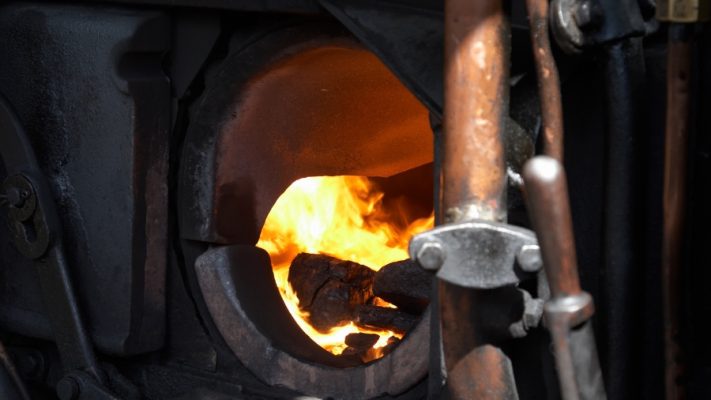
3. Furnace design in boiler design
Furnace design is a critical aspect of optimizing boiler performance, particularly in terms of heat transfer efficiency and fuel combustion effectiveness. This process involves selecting appropriate burners, determining the furnace shape, and calculating its volume to ensure efficient and safe combustion.
3.1. Burner selection and furnace shape design
The first step in furnace design is selecting a burner that matches the calculated fuel requirements. The burner must be compatible with the type of fuel (e.g., gas, oil, coal) and the boiler’s thermal capacity. It should provide a stable flame that is evenly distributed within the furnace to prevent energy losses or operational inefficiencies caused by flame misalignment.
Once the burner is selected, the furnace shape design must optimize space for the combustion process. The shape of the furnace front wall is determined based on the burner’s dimensions and the length and size of the flame. The wall structure should allow adequate space for the distribution of fuel and air, enabling complete and thorough combustion.
3.2. Furnace volume calculation
nother crucial element in furnace design is calculating the required volume to accommodate sufficient fuel and air for the combustion process. The furnace volume is determined using the Volumetric Heat Release Rate (VHRR), which helps establish the space needed for combustion and efficient heat transfer. VHRR is a key factor in choosing the furnace size, ensuring adequate fuel and air supply for efficient combustion.
The furnace volume calculation typically involves factors such as boiler capacity, the heat released by the fuel, and the air-to-fuel ratio. Accurate volume calculation not only impacts combustion efficiency but also ensures safety by preventing overheating or incomplete combustion.
By combining precise burner selection, shape optimization, and volume calculation, furnace design can significantly enhance boiler performance, reliability, and safety.
4. Calculating furnace exit gas temperature (FEGT)
The Furnace Exit Gas Temperature (FEGT) refers to the temperature of exhaust gases as they leave the furnace and enter subsequent sections of the boiler. FEGT directly impacts the efficiency of downstream heat exchangers, particularly the superheater. A higher FEGT increases heat transfer to the superheater, thereby improving steam generation efficiency. However, excessively high FEGT can lead to unnecessary heat loss and potentially reduce the lifespan of boiler components due to corrosion and oxidation.
When calculating FEGT during boiler design, several factors must be considered, including fuel consumption, combustion efficiency within the furnace, and exhaust gas characteristics such as flow rate and temperature. FEGT also depends on the required steam temperature. If high steam temperatures are needed, the FEGT must be controlled to ensure sufficient heat is available for heating the steam to the desired level without causing excessive energy wastage.
5. Calculating effective projected radiant surface (EPRS)
The Effective Projected Radiant Surface (EPRS) refers to the surface area within the furnace where heat from exhaust gases is directly absorbed by the tubes in the heat exchange system. EPRS includes the surface area of radiant tubes and any membrane walls or shields designed to absorb heat from hot exhaust gases. EPRS plays a crucial role in transferring heat from exhaust gases to water or steam in the boiler. Hence, it must be designed to maximize heat absorption without compromising combustion efficiency.
To calculate EPRS, key parameters include FEGT, the heat absorption capacity of the radiant tubes, and the heat transfer rate between exhaust gases and these surfaces. A larger EPRS enhances heat absorption, improving boiler efficiency. However, the surface area must be carefully optimized to avoid overloading the system and disrupting heat distribution within the boiler.
This design balance ensures efficient thermal performance while maintaining safety and longevity in boiler operation.
6. Calculation of heat transfer surface area
The Heat Transfer Surface Area represents the areas in a boiler, such as the tubes in the convection bank, where heat is transferred from flue gases to water or steam. This area must be sufficiently large to ensure efficient heat transfer to produce the required amount of steam. The surface area is calculated based on factors like flue gas exit temperature (FEGT), the heat required for steam production, and the thermal conductivity of the heat exchange surfaces in the boiler.
The calculation involves determining the required heat exchange based on the steam capacity and steam temperature requirements. With the FEGT and the necessary heat for steam production established, the required heat transfer surface area can be computed. The area must be large enough to maintain efficient heat transfer without compromising boiler performance.
7. Sizing the steam drum
The steam drum is a critical component of a boiler system, responsible for separating steam from water and maintaining system stability during steam production. Its size must be carefully calculated considering factors such as steam capacity, circulation ratio, load fluctuations, and steam-water separation requirements. Below is a detailed analysis of the factors influencing steam drum sizing.
7.1. Steam capacity at maximum continuous rating (MCR)
Steam capacity at MCR is the first factor to consider when sizing the steam drum. MCR specifies the maximum amount of steam the boiler can produce per hour without compromising efficiency or causing system damage. The steam drum must be large enough to accommodate and separate sufficient steam-water mixture during operation. The steam capacity requirement is divided by other factors like flow rate and temperature to determine the drum size.
7.2. Circulation ratio
The circulation ratio is the ratio of water circulating in the system to the amount of steam produced. It directly affects the stability and efficiency of heat transfer in the boiler. A low circulation ratio can lead to overheating or inadequate steam-water separation, while a high ratio can reduce steam generation efficiency.
When designing the steam drum, the circulation ratio must be calculated to ensure sufficient water is available to absorb heat without overloading the steam drum. This ensures effective steam separation and stable steam quality.
7.3. Load fluctuations
Load fluctuations refer to changes in steam demand during boiler operation. The boiler must respond to these changes without compromising steam quality or efficiency. The steam drum must be designed to hold enough water to handle load fluctuations without causing shortages or overflows.
A boiler system with an undersized steam drum may struggle to adjust to rapid load changes, while an oversized drum could lead to wasted energy and increased investment costs.
7.4. Steam-Water separation equipment
Steam-water separation equipment in the steam drum plays a vital role in ensuring high-quality steam by effectively separating water and steam. The steam drum must include components such as separators, demisters, and scrubbers to eliminate impurities and prevent water carryover into the steam.
The drum design should provide adequate space and proper arrangement of separation equipment to enhance the separation process. This not only improves steam quality but also protects downstream components like superheaters and turbines from damage caused by water or impurities.
8. Calculation of economizer surface area
The economizer in a boiler system is crucial for recovering heat from flue gases, reducing heat losses, and improving boiler efficiency. The calculation of its surface area involves several key factors, including flue gas temperatures, sulfur content in the fuel, and the minimum flue gas exit temperature to avoid dew point corrosion.
To calculate the economizer surface area, the flue gas inlet and outlet temperatures must be determined. The inlet temperature depends on the combustion product temperature, while the outlet temperature is influenced by the economizer’s heat exchange efficiency. To prevent dew point corrosion, the flue gas outlet temperature should be maintained above the dew point temperature, where water vapor in the gas condenses and causes metal corrosion.
Standards such as TCVN for boiler installations and ASME Section I require strict control over flue gas temperatures and quality to mitigate corrosion issues and enhance economizer performance. Proper design and material selection ensure long-term efficiency and reliability of the economizer in the boiler system.
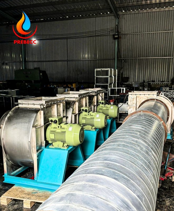
9. Fan power calculation
The ID fan (Induced Draft fan) and FD fan (Forced Draft fan) are critical components in a boiler system, responsible for regulating airflow during the combustion process and venting exhaust gases. Calculating the power of these fans requires an understanding of airflow rates and exhaust gas pressures.
The FD fan must supply sufficient air to sustain combustion, while the ID fan is tasked with drawing exhaust gases out of the system. The power required for both fans depends on the airflow needed for combustion and the system’s pressure maintenance.
Fan power can be calculated using the formula:
P = (Q⋅ΔP) /
Where:
- P is the fan power,
- Q is the airflow rate,
- ΔP is the pressure difference, and
- η is the fan efficiency.
These requirements are specified under the ASME PTC 4-2013 standards for fan performance testing and calculation.
10. Determining chimney height in boiler design
Chimney height in a boiler system depends not only on its design but also on exhaust gas characteristics, particularly the SO₂ (sulfur dioxide) emissions from fuel combustion. SO₂ emissions significantly influence chimney height to ensure effective gas dispersion and minimize environmental pollution.
The chimney height must be calculated to disperse exhaust gases far from production areas and residential zones. This calculation typically involves formulas that account for flue gas flow rates and meteorological factors. Standards such as TCVN 5949:2010 and ASME Section I dictate that chimney height must meet environmental protection requirements and ensure system safety.

11. Accessory calculation and installation
Installing boiler accessories like safety valves, water level gauges, and other components must strictly adhere to technical standards and safety regulations. Safety valves must be designed to prevent overpressure during operation, while water level gauges are essential for monitoring water levels accurately to avoid the risks of water shortage.
Additionally, thermal expansion of components must be accounted for during installation. As boilers operate, changes in temperature and pressure cause material expansion, which must be calculated to ensure the longevity and safety of the accessories during operation.
12. Stress analysis
Stress analysis is a crucial aspect of boiler design to ensure the durability and safety of pressure-retaining components such as the boiler shell, heat-exposed parts, and load-bearing structures. Stresses can arise from factors like rapid temperature changes, sudden pressure fluctuations, and mechanical impacts.
To calculate stresses, mechanical analysis methods and specific formulas are used to determine forces acting on individual components. The stress design requirements are outlined in the ASME Boiler and Pressure Vessel Code (BPVC), especially in Section VIII, which addresses pressure equipment design. This ensures components do not fail due to excessive stress during operation.
13. Development of protection and control systems
Protection and control systems in boilers are vital for ensuring safe operations. These systems include devices like temperature controllers, pressure regulators, water level monitors, and fault detection systems. Standards such as NFPA-85 require a Burner Management System (BMS) to monitor and control fuel combustion, protecting the boiler from potential hazards.
Furthermore, the Distributed Control System (DCS) must be standardized for seamless integration with other system components, ensuring safe and efficient operation.