Boiler valves play a crucial role in steam and hot water systems by regulating pressure, temperature, and flow. Not only do they ensure efficient operation, but they also serve as vital safety components, preventing overpressure conditions and aiding in system maintenance. Learn more about common types of boiler valves and their functions in this article.
1. Ball Valve
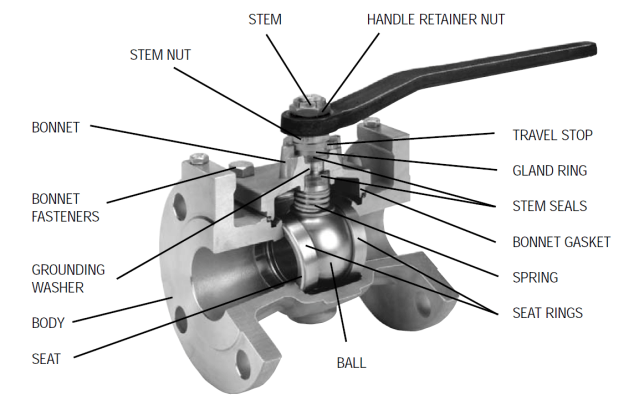
1.1. Structure and working principle
A ball valve is a quick-acting shut-off valve that operates with a 90-degree turn. It consists of a hollow, perforated ball that rotates within the valve body. When the hole in the ball aligns with the flow direction, the valve is fully open, allowing the fluid to pass through. Conversely, when the ball is rotated 90 degrees, the flow is completely blocked.
Ball valves are widely used in boiler systems, particularly in applications requiring rapid shut-off, such as steam supply lines or feedwater systems. The sealing seats are typically made of soft materials to ensure tight shut-off, though metal or plastic materials may also be used depending on the application. However, ball valves are not ideal for throttling, as partial opening can cause excessive wear and shorten the valve’s lifespan.
When a ball valve is in the open position, pressure drop may occur due to the misalignment between the flow path and the ball’s bore, potentially reducing the efficiency of steam or water transfer in a boiler system.
1.2. Advantages
Simple design and easy operation: Ball valves are compact, with fewer moving parts, making installation, maintenance, and operation straightforward—ideal for boiler systems with space constraints.
Quick shut-off: A 90-degree turn is all that is required to transition between open and closed states, minimizing response time. This is particularly useful in systems requiring instant flow control.
High pressure and temperature resistance: Premium-grade ball valves, especially those made from stainless steel or carbon fiber, can withstand high pressures (up to 30 MPa) and temperatures, making them suitable for demanding boiler environments.
Excellent leak prevention: The tight-sealing design, often incorporating resilient seats, minimizes steam or high-pressure gas leakage, enhancing both safety and system efficiency.
Durability: With robust construction, ball valves offer long service life with minimal maintenance, reducing operational costs for industrial applications.
1.3. Disadvantages
Not suitable for flow regulation: While ball valves can be used for flow control, they are not ideal for precise adjustments. Partial opening can cause turbulence and accelerate wear, reducing efficiency.
Potential wear in high-pressure environments: Due to the rapid open/close mechanism, friction between the ball and the sealing seats can lead to wear, especially in continuous high-temperature and high-pressure applications.
Unsuitable for viscous or contaminated fluids: In boiler systems containing debris or impurities, ball valves can become clogged or suffer sealing seat damage. Gate or globe valves may be better alternatives in such cases.
Pressure drop when partially opened: When not fully open, pressure differentials at the inlet and outlet can decrease system efficiency. This is less of an issue for on/off applications but significant for flow regulation.
2. Gate Valve
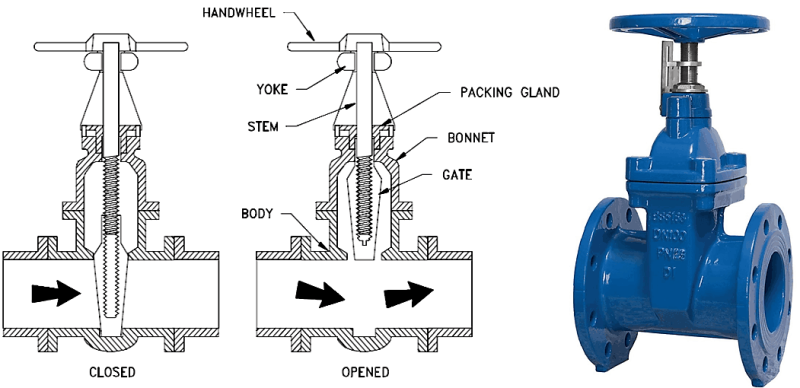
2.1. Structure and working principle
A gate valve operates via a sliding gate mechanism that moves vertically to control fluid flow. When fully open, the gate retracts entirely, providing an unrestricted flow path with minimal pressure loss. When closed, the gate lowers to block the flow completely.
In boiler systems, gate valves are commonly installed in main steam lines or feedwater lines where large flow rates need to be managed. Thanks to their streamlined flow design, gate valves help maintain stable pressure and minimize energy loss.
2.2. Advantages
Minimal pressure loss: When fully open, the internal flow passage closely matches the pipeline diameter, reducing pressure drops—critical in high-pressure steam transmission.
Durable and low-maintenance: With a simple design and few moving components, gate valves are mechanically reliable and require minimal maintenance.
Prevents pressure surges: The gradual opening/closing process reduces pressure shocks and vibrations in the piping system, which is essential for high-pressure steam applications.
Versatile applications: Gate valves accommodate various fluids, including steam, hot water, thermal oil, and even viscous substances, making them ideal for diverse industrial boiler systems.
Compact design for space-limited installations: The slim profile of gate valves allows for installation in tight spaces without compromising performance.
2.3. Disadvantages
Not suitable for throttling: Gate valves function best when fully open or closed. Partial opening can cause turbulent flow, vibration, and accelerated wear, reducing both valve life and system performance.
Slower operation: The need to move a large gate means that gate valves take longer to open and close compared to ball or globe valves, making them less ideal for applications requiring rapid shut-off.
Potential noise when not fully closed: If not properly sealed, gate valves may cause vibration and noise in the piping system, which can be problematic for noise-sensitive operations.
High maintenance and repair costs in case of failure: Although they require infrequent maintenance, gate valves can be expensive to repair or replace when damaged due to their internal complexity, particularly in large-diameter or high-pressure applications.
3. Plug valve
3.1. Structure and working principle
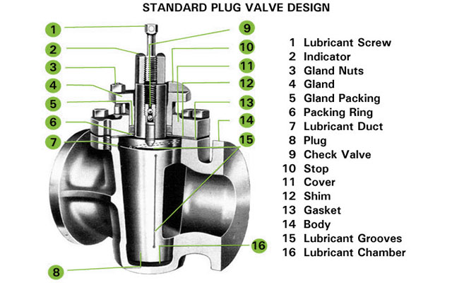
A plug valve is a quarter-turn valve that uses a cylindrical or conical plug to regulate fluid flow. The plug has a hollow passage through its center, which aligns with the flow direction when open and rotates 90 degrees to block flow when closed.
The plug valve’s rotating mechanism ensures a fast shut-off response, making it ideal for systems requiring rapid operation.
When the lever is parallel to the pipeline, the passage inside the plug aligns with the flow, allowing fluid to pass.
When rotated 90 degrees, the passage becomes perpendicular to the pipeline, blocking flow entirely.
Wear and Mitigation Solutions
During partial opening, swirling flow patterns can cause pressure drops and uneven wear on the plug’s surface due to fluid turbulence. Additionally, the friction between the plug and valve body during operation can lead to gradual degradation over time.
To mitigate wear, two key solutions are commonly employed:
- Lubricated Plug Valves – Some plug valves incorporate lubrication ports that apply specialized oil to reduce friction between the plug and valve body, enhancing sealing performance and extending service life.
- Lift-Type Plug Valves – Advanced designs allow the plug to lift slightly before rotation, minimizing friction and maintaining sealing integrity when closed.
3.2. Advantages
Simple design with superior sealing: With fewer moving parts, plug valves offer high reliability and minimal leakage risk.
Fast operation: The quarter-turn mechanism enables instant shut-off, making them ideal for emergency shut-down applications.
Versatile applications: Plug valves can handle steam, hot water, thermal oil, and gas, making them highly adaptable for boiler systems.
Durable and low-maintenance: Their solid construction provides long service life and resistance to high-pressure conditions.
3.3. Disadvantages
Higher operating torque: The full-contact rotation design requires greater force to operate, especially for larger-diameter plug valves.
Limited throttling capability: Plug valves are primarily designed for on/off control, and partial opening can cause turbulence and accelerated wear on sealing surfaces.
Each boiler valve type serves distinct functions in a steam or hot water system. Selecting the appropriate valve depends on operational needs, pressure conditions, and fluid characteristics. Understanding their advantages and limitations ensures safe, efficient, and cost-effective boiler system management.
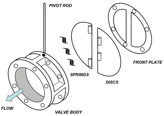
4. Butterfly valve
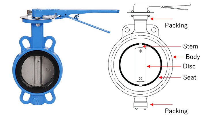
4.1. Structure and working principle
The butterfly valve operates on a 90° rotation mechanism to control flow. When force is applied to the valve handle or actuator, the torque is transmitted to the valve stem, causing the disc to rotate as follows:
Valve opening: Rotating the handle counterclockwise aligns the valve disc parallel to the pipeline, allowing the fluid to flow through with minimal obstruction.
Valve closing: Rotating the handle clockwise turns the disc perpendicular to the flow, completely blocking the passage of the fluid.
*Important notes:
- The butterfly valve operates optimally when fully opened or fully closed. If used for flow regulation within the range of 15° – 75°, the fluid may create strong vortices, leading to uneven wear on the valve disc surface and reducing its lifespan.
- During operation, it is crucial to install the appropriate valve type that matches the system’s pressure and temperature conditions to prevent premature failure.
4.2. Advantages
Butterfly valves are widely used in boiler systems due to their compact design, simple operation, and low cost. Some key advantages include:
- Compact design and easy installation: Compared to other industrial valves such as gate valves or globe valves, butterfly valves are significantly smaller and lighter. This makes installation and maintenance easier, especially in confined spaces within boiler systems.
- Quick opening/closing capability: With a 90° rotation mechanism, butterfly valves can transition from closed to open (or vice versa) in a short time. This feature is highly beneficial in systems requiring rapid response, minimizing the time needed for steam flow adjustments.
- Low pressure loss when fully open: In the fully open position, the valve disc aligns with the flow direction, allowing steam or fluid to pass through with minimal resistance. This helps maintain stable system pressure and reduces energy loss.
- Low investment and maintenance costs: Compared to other industrial valves, butterfly valves are more cost-effective while still providing good performance in various applications. Their simple structure makes maintenance and replacement easy, reducing long-term operating costs.
4.3. Disadvantages
Despite their advantages, butterfly valves also have certain limitations, especially in high-pressure and high-temperature boiler systems:
- Not suitable for flow regulation: When partially open (within 15° – 75°), the valve disc remains in the steam flow, creating turbulence and pressure drops. This not only decreases system efficiency but also causes uneven wear on the valve disc, shortening its lifespan.
- Lower sealing capability in high-pressure conditions: In high-pressure boiler systems, butterfly valves may not achieve complete sealing as effectively as globe valves or plug valves. Leakage can occur if the sealing surface wears out or deteriorates under harsh operating conditions.
- Limited performance in extreme temperatures and pressures: When operating temperatures exceed 300°C or pressures exceed 25 bar, the sealing efficiency of butterfly valves decreases significantly. In such environments, valves with better heat and pressure resistance, such as globe or gate valves, are more suitable.
5. Globe valve
5.1. Structure and working principle
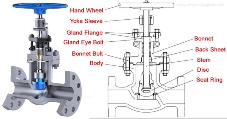
Globe valves are a type of linear motion valve commonly used in boiler systems to regulate steam and feedwater flow. A distinctive feature of globe valves is that the fluid flow path forms an “S” shape, meaning the fluid must change direction twice when passing through the valve body. This design results in significant pressure loss but allows for precise flow control.
The main components of a globe valve include:
- Valve body: Made from high-temperature-resistant materials such as ductile iron, alloy steel, or stainless steel, suitable for high-pressure and high-temperature conditions in boilers.
- Bonnet: Protects internal components and can be removed for maintenance.
- Disc: Moves vertically to control the flow of steam or water through the system.
- Seat: Directly contacts the disc, ensuring tight closure and minimizing leakage.
- Stem: Connects the handwheel to the disc, transmitting force for valve operation.
- Actuator (if applicable): Can be operated manually via a handwheel or automatically through pneumatic or electric control systems.
Operating principle:
- Rotating the handwheel counterclockwise lifts the valve disc, creating an opening for fluid to flow through.
- Rotating the handwheel clockwise lowers the disc, pressing it against the seat to stop the flow.
- Due to the curved flow path inside the valve body, the outlet pressure is always lower than the inlet pressure, causing a pressure drop but providing better flow control.
5.2. Advantages
Excellent flow regulation capability: The design of the globe valve allows precise control of steam and feedwater flow, which is crucial in boiler systems where pressure and temperature fluctuate constantly.
High sealing performance: Since the disc presses directly against the seat in a vertical motion, leakage is significantly lower than in other valves such as butterfly or gate valves. This helps maintain stable pressure within the boiler system.
Durability in frequent operation: When operated correctly, globe valves experience less wear and damage compared to other valve types, as the vertical closing motion minimizes side friction.
Suitable for high-pressure and high-temperature conditions: In boiler systems where fluid temperatures reach several hundred degrees Celsius and pressure is high, globe valves made from heat-resistant materials can function reliably and withstand harsh conditions.
Easy maintenance and replacement: The design of the globe valve allows for bonnet removal to inspect and replace the disc or seat without removing the entire valve from the system.
Flexible installation: Can be installed in various positions and easily integrated with automatic control systems.
5.3. Disadvantages
High pressure loss: Since the fluid must change direction twice when passing through the valve, the outlet pressure is significantly reduced. This can affect the efficiency of steam and water distribution in the boiler system.
Higher cost compared to other valve types: Compared to butterfly or gate valves, globe valves have a more complex structure, resulting in higher initial investment costs.
Requires significant operating force: Large-size globe valves require considerable force to open and close. Without an actuator, manual operation can be challenging.
Larger size and weight: For the same nominal diameter (DN), globe valves are bulkier and heavier than other valve types, requiring more installation space.
Cavitation risk: When pressure changes abruptly, especially in high-pressure steam flow, air bubbles may form and collapse, leading to cavitation damage on the valve seat. When installing globe valves in boiler systems, the flow direction should be carefully considered to minimize cavitation effects.
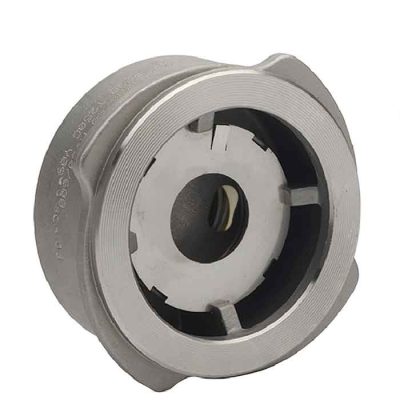
6. Disc check valve
The disc check valve, also known as a non-return valve, is designed to allow fluid to flow in only one direction while preventing reverse flow. Due to this characteristic, check valves are widely used in critical systems, especially in steam systems where backflow can severely impact equipment and operational efficiency.
6.1. Types of check valves
6.1.1. Lift Check Valve
This type of check valve operates based on gravity. When the fluid flows in the forward direction, the flow pressure lifts the valve disc off the seat, allowing fluid to pass through. Conversely, when the flow reverses, gravity combined with backpressure forces the disc back onto the valve seat, blocking the return flow.
Lift check valves are commonly used in systems with high flow velocity and stable pressure. Their rapid opening and closing mechanism helps mitigate water hammer – a frequent issue in steam systems. However, since their operation relies on gravity, lift check valves are typically suitable for vertical or slightly inclined installations.
6.1.2. Swing Check Valve
The swing check valve features a disc attached to a hinge, allowing it to pivot around a fixed axis. When fluid flows in the forward direction, the flow pressure pushes the disc open, enabling passage. When the flow reverses, the backflow pressure forces the disc to swing back into the closed position, sealing against the valve seat and preventing reverse flow.
This valve type has the advantage of lower pressure loss compared to lift check valves and can be installed in both horizontal and vertical orientations. However, a key drawback is its longer closing time due to the inertia of the disc, which may lead to water hammer in high-pressure systems.
6.1.3. Spring-loaded Check Valve
The spring-loaded check valve incorporates a spring mechanism that keeps the valve disc in a closed position. To open the valve, the fluid must generate sufficient pressure (known as “cracking pressure”) to overcome the spring force. When the flow pressure decreases or reverses, the spring automatically pushes the disc back into the closed position, effectively preventing backflow.
Thanks to this design, spring-loaded check valves can be installed in any orientation without being affected by gravity. Their rapid closing capability significantly reduces the risk of water hammer. As a result, this type of valve is commonly used in high-pressure systems or applications requiring quick response times.
6.1.4. Diaphragm Check Valve
The diaphragm check valve utilizes one or more flexible diaphragms arranged to open only when the fluid flows in the forward direction. When backflow occurs, the diaphragm automatically seals against the valve seat, preventing reverse flow.
This valve type offers exceptional sealing performance, minimizing leakage even when handling highly viscous fluids or fluids containing small solid particles. Additionally, since it lacks moving parts such as stems and discs, the diaphragm check valve has a longer lifespan and requires less maintenance than other check valve types. However, it is only suitable for medium- and low-pressure applications, as the diaphragm material has limited durability under high-pressure conditions.
6.2. Applications in Boiler Systems
In boiler systems, check valves play a crucial role in protecting equipment and preventing backflow, which could otherwise damage boilers, feed pumps, and pipelines.
Lift check valves and swing check valves are commonly used in main steam pipelines where minimal pressure loss and high steam flow rates are required.
Spring-loaded check valves are widely used in boiler feedwater systems to prevent hot water from flowing back into the pump, protecting it from overheating.
Diaphragm check valves are used in applications requiring high sealing performance, such as condensate recovery systems, where they help prevent steam from escaping.
Selecting the appropriate type of check valve for a steam system not only optimizes operational efficiency but also extends equipment lifespan, reduces maintenance costs, and mitigates issues such as water hammer and sudden pressure loss.
>>>Boiler fittings and mountings: Essential components for safe operation