Heat exchangers play a critical role in the thermal and energy systems of various heavy industries, from petrochemical to food processing. However, their efficiency and service life can only be maintained when operated and maintained in strict accordance with technical standards.
Among these, TEMA — the Tubular Exchanger Manufacturers Association standard — serves as an indispensable guide, providing detailed instructions on everything from cleaning, bolt tightening, gasket replacement, to failure handling procedures. This article outlines the key requirements for operating and maintaining heat exchangers according to TEMA.
1. TEMA-Based guidelines for operating heat exchangers
In industrial systems, particularly in the petrochemical, energy, and food processing sectors, heat exchangers are vital components that must be operated correctly to ensure safety, efficiency, and longevity. Below are operation guidelines based on TEMA standards, including recommended operating conditions, startup/shutdown procedures, and proper bolting practices.
1.1. Design and operating conditions
Heat exchangers must not be operated under conditions exceeding those listed on the nameplate. Strict adherence to design parameters is essential for safe and stable operation and to avoid potential damage.
1.2. Operation procedures
Before commissioning a heat exchanger, consult the engineering drawings, specification sheets, and nameplate to understand all specific instructions. In addition, comply fully with all relevant local safety and health regulations. For fixed tubesheet heat exchangers, improper startup or shutdown can cause leaks at tube-to-tubesheet joints or bolted flange connections.
1.2.1. Startup procedure
For units with a removable tube bundle, initiate flow with the cold-side fluid, then gradually introduce the hot-side fluid into the system.
During startup, open all vent valves to purge air and ensure the unit is completely filled with liquid.
For fixed tubesheet heat exchangers, manage fluid introduction to minimize thermal expansion differentials between the shell and tubes.
1.2.2. Shutdown procedure
For removable tube bundle units, reduce hot-side fluid flow first, then shut down the cold-side.
If the cold fluid must be stopped suddenly, immediately shut off the hot fluid to prevent thermal shock or equipment damage.
The unit should be drained if there is a risk of freezing or corrosion during downtime.
For systems using steam, drain condensate during both startup and shutdown to prevent water hammer.
For water-cooled units, use compressed air to blow out residual water after draining to avoid internal water retention.
1.2.3. Preventing thermal shock
Avoid sudden exposure of the heat exchanger to extreme temperature changes. Do not introduce hot fluid while the exchanger is cold, or vice versa.
1.2.4. Bolted joints
Although heat exchangers are hydrostatically tested at the factory, gasketed joints may relax during transport or installation.
All accessible bolted connections may require re-torquing after installation and again after reaching operating temperatures.
Key considerations:
- Bolt preload may reduce after initial tightening due to creep or gasket relaxation, especially with soft materials.
- Over-tightening can deform bolts, particularly small-diameter or low-yield materials like stainless steel.
- Refer to Appendices N and P of ASME PCC-1 for bolt reuse and flange leakage troubleshooting.
Bolt stress and torque values should ensure sufficient gasket sealing force without exceeding flange limits. Accepted methods include:
- Field experience
- Gasket manufacturer recommendations
- ASME Code Appendix Sa, PCC-1 Section 10, Appendix O
- WRC Bulletin 538
- The Joint Component Approach from ASME PCC-1-0-4 or WRC-538 (recommended during flange design, as this may increase flange thickness)
Gasket seating stress reference values may be sourced from:
- Gasket manufacturers
- PVP2013-97900 (non-asbestos sheet gaskets)
- PVP2014-28434 (GMGC, CMGC, and spiral wound gaskets)
To convert bolt stress to torque, refer to ASME PCC-1 Section 12.
1.2.5. Recommended bolting procedure
Surface Preparation: All gasket contact surfaces must be clean, dry, and free of oil or debris. Do not use grease to hold the gasket during installation. Remove any adhesive tape used during transport.
Thread and Surface Cleaning: Clean all bolt threads, nut faces, and flange contact areas. Remove burrs and surface imperfections if present.
Proper Lubrication: Lubricate threads, nuts, and contact surfaces according to ASME PCC-1 Section 7.
Flange Alignment: Ensure even flange compression across the gasket per ASME PCC-1 Section 5 and Appendix E.
Cross-Bolting Pattern: Apply torque in at least three increments, increasing each pass, using a cross bolting pattern or as per ASME PCC-1 Sections 8–11.
Circular Chase Pattern: After cross-pattern tightening, use a circular pattern until no further nut rotation occurs, ensuring uniform bolt load.
2. Heat exchanger maintenance
2.1. Equipment inspection
Internal and external inspections of the heat exchanger should be carried out periodically, with frequency determined based on operational experience. Failure to clean the tubes regularly may result in complete blockage of some tubes, leading to severe thermal stress, leakage at joints, or structural damage to related components. If the unit is equipped with sacrificial anodes, their condition should be inspected to determine whether cleaning or replacement is required.
2.1.1. Signs of Fouling or Scaling
Heat exchangers susceptible to fouling or scaling must be cleaned regularly. Even a thin layer of deposits can significantly reduce the heat transfer efficiency of the tubes. Common indicators include a sudden increase in pressure and/or a noticeable decline in performance—both of which suggest that cleaning is necessary. Before proceeding, check for any trapped air or vapor in the system to rule out other causes of performance degradation. Since accumulated deposits become harder to remove over time, cleaning intervals should not be excessively long.
2.1.2. Disassembly for inspection or cleaning
Before disassembling the unit, ensure it is fully depressurized, vented, drained of all liquids, and that any hazardous substances have been neutralized and/or cleaned out. The typical disassembly steps for tube-side inspection and cleaning are as follows:
Front End Stationary Head
- Type A, C, D, N: Remove the channel cover
- Type B: Remove the bonnet
Rear End Head
- Type L, Nh, P: Remove the channel cover
- Type M: Remove the bonnet
- Type S, T: Remove the shell cover and floating head cover
- Type Wh: Remove the channel cover or bonnet
2.1.3. Detecting tube leaks
The following methods can be used to detect punctured tubes or leaking tube-to-tubesheet joints. Typically, the entire front face of the tubesheet is accessible for inspection. Leak locations can be identified at the point where water escapes:
Units with removable channel covers: Remove the cover and conduct a hydrostatic pressure test on the shell side.
Units with bonnet-type front heads:
For fixed tubesheet units where the tubesheet is part of the shell, remove the bonnet and perform a pressure test.
For units with non-integral tubesheets or removable tube bundles, remove the bonnet, reattach the tubesheet to the shell, or install a suitable test flange or blind cover, then conduct a hydrostatic test.
Floating head units (Type S or T): Remove the channel cover or bonnet, then remove the shell and floating head cover. Install a test ring with appropriate sealing gaskets. If a test ring is unavailable, the shell can be removed and the tube side pressurized to identify leak points by observing the tube lanes. Extreme caution must be taken during pressure testing in disassembled conditions to avoid damaging expansion joints or tube connections.
The minimum metal temperature during hydrostatic testing should be 60°F (16°C) or as required by the applicable standard.

2.2. Tube bundle removal and handling
The tube bundle should be withdrawn from the fixed tubesheet end as specified in the engineering drawings. Prior to removal, all components such as retaining rings, split rings, gaskets, and sealing elements must be removed.
If the fixed tubesheet has tapped holes, eye bolts may be used to assist with tube bundle extraction. If no tapped holes are available, a metal rod may be inserted through several tubes and attached to a load-bearing steel plate on the floating tubesheet side. A protective material should be placed between the steel plate and the tube ends to prevent damage.
Hooks or sharp tools must not be used to pull the tube bundle, as they may cause damage. The tube bundle should be supported on a frame or sliding skid. For horizontal bundles, appropriate slings or cables should be used for lifting. Care must be taken to avoid bending or damaging the baffles during handling. All surfaces in contact with gaskets and sealing materials must be carefully protected, as damage to these areas is difficult to repair.
2.3. Tube bundle cleaning
2.3.1. Cleaning methods
To maintain efficient heat transfer, heat exchange surfaces must be kept clean. The equipment design should accommodate convenient periodic cleaning.
Cleaning may be done using mechanical or chemical methods, depending on the type of fouling and plant conditions. Common methods include:
Circulation of hot oil or light distillate at high velocity through the tubes or shell to remove sludge or soft deposits.
Washing certain salts with clean hot water.
Use of commercial chemical cleaners when hot oil or water is not effective.
High-pressure water jet cleaning.
Mechanical removal of hard scale, coke, or deposits using rotary brushes, scrapers, or other mechanical devices.
Hiring professional cleaning services: These providers can analyze the fouling characteristics, select appropriate solvents or inhibited acid solutions, and provide the necessary equipment and personnel to complete the cleaning process.
2.3.2. Precautions for heat exchanger cleaning
(1) Do not clean tubes by blowing steam through individual tubes, as localized heating may cause differential expansion, tube distortion, or loosening of the tube-to-tubesheet joint.
(2) Exercise caution during mechanical cleaning to avoid tube damage.
(3) Cleaning chemicals must be compatible with the heat exchanger materials.
(4) Some cleaning methods, particularly hot fluid circulation through the tubes, can create large temperature differentials between shell and tube sides. This may damage fixed tubesheet exchangers and should be avoided unless such differential was accounted for in the original design.
2.4. Tube expanding
A proper tube expander should be used to re-expand leaking tube joints. Care must be taken not to over-expand the tubes during this process.
2.5. Gasket replacement
The gasket surface and its mating surface must be thoroughly cleaned and free from scratches or defects. Before tightening bolts, ensure the gasket is properly seated. It is recommended to use new gaskets each time the heat exchanger is opened for any reason, to avoid leakage and prevent damage to gasket contact surfaces.
Soft gasket materials, such as non-metallic gaskets, may become dry and brittle over time and will not ensure proper sealing if reused. Metallic or jacketed gaskets, once compressed, conform to the flange surface and harden. Reusing them may lead to leakage or damage to the sealing surface. Gaskets with graphite coatings are usually damaged upon disassembly and are not reusable.
Bolt and flange connections are designed for specific gasket types. Replacing with incompatible gasket structures or dimensions may lead to leakage and surface damage. If gasket type changes are necessary, compatibility must be ensured and consultation with the manufacturer is strongly recommended.
If leakage occurs at gasketed joints, it must be addressed immediately to prevent damage to sealing surfaces.
When using jacketed gaskets with tongue-and-groove joints (without nubbin), ensure the tongue contacts the flat surface of the gasket jacket. If the gasket has a nubbin, the nubbin must contact the flat sealing face.
2.6. Metal diaphragm installation procedure
(1) Position the diaphragm correctly and secure it tightly to eliminate any gaps between the diaphragm and the equipment surface to be welded. This may be done using a cover plate, clamps, or other means to ensure the diaphragm remains stationary during final bolt tightening and to prevent weld cracking.
(2) Weld the diaphragm to the equipment, then inspect the weld using the liquid penetrant testing method.
(3) Install the cover plate and tighten the bolts to the specified torque or preload.
(4) After bolt tightening, re-inspect the weld with liquid penetrant testing.
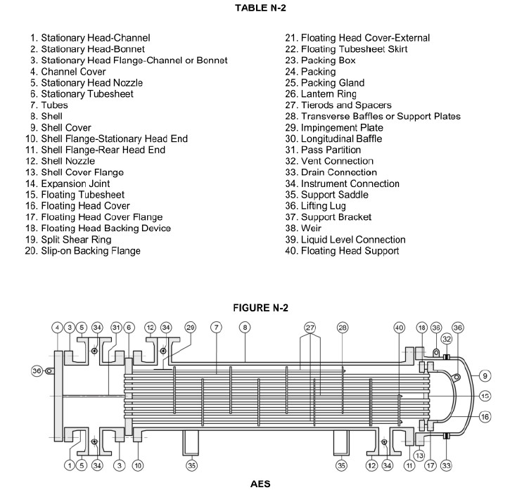
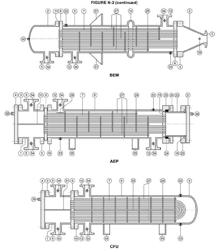
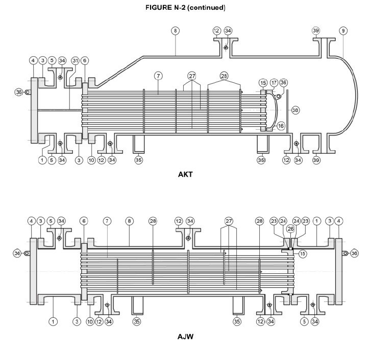
2.7. Spare and replacement parts
Purchasing spare or replacement parts from the manufacturer is more efficient when the correct part name is provided according to Table N-2, Section 1 of this standard, along with the serial number, model, size, and all nameplate information. It is recommended to purchase replacement parts directly from the original equipment manufacturer (OEM).
2.8. Tube plugging
In U-tube or special design heat exchangers, removal and replacement of damaged tubes may not be feasible. In such cases, tubes can be plugged using tapered plugs with ferrules or plain taper plugs, either welded or unwelded.
However, excessive plugging of tubes may reduce heat transfer efficiency, increase pressure drop, and/or adversely affect the mechanical integrity of the unit. The user is responsible for removing plugs and cleaning the bundle before sending it to a workshop for repair.
3. Changes of heat exchanger configuration
During operation, it may become necessary to modify the heat exchanger configuration — including upgrading materials, increasing design pressure or temperature limits, or changing the type of gasket during component replacement or maintenance. These modifications may arise from a desire to improve performance, to take advantage of new alloy materials, to adapt to changes in the process system, or to resolve existing technical issues — while also considering economic feasibility.
When making any changes to the components, a comprehensive evaluation must be performed to assess their impact on the overall design of the heat exchanger. Prior to implementing any modification, the applicable regulations of the local authorities where the equipment is installed must be reviewed and followed. Additionally, full compliance with the requirements of the governing Code and TEMA Standards is mandatory.
Specific factors requiring careful consideration include:
- Flange pressure ratings
- Material thickness requirements
- Unsupported tube length limits
- Nozzle inlet/outlet locations on channel heads
- Pass partition plate configurations
- Minimum clearance between the removable tube bundle head and the shell
These elements must be checked and validated against the original design intent and applicable standards to ensure continued mechanical integrity and safe operation of the unit.
>> Contact us for Heat Exchanger design consultantation here
Or Send quote request information directly to email: info@prebecc.com