Selecting the correct size of industrial pipes is crucial for ensuring system efficiency, safety, and longevity. Pipe sizing is determined not only by technical requirements but also by the specific challenges posed by the transported fluid or gas. An incorrect pipe size can lead to system failures, energy losses, and high repair costs.
This article provides an overview of the key factors influencing industrial pipe sizing, including the properties of the fluid/gas, viscosity, density, pressure, and temperature.
1. Properties of the transported Fluid/Gas
1.1. Viscosity
Viscosity measures a fluid’s resistance to flow. High-viscosity fluids experience greater internal friction between layers, reducing flow rates within pipes. In such cases, larger pipe diameters are necessary to minimize pressure loss and maintain flow efficiency.
Conversely, low-viscosity fluids can flow easily through smaller pipes without significantly increasing pressure loss. Assessing viscosity helps determine the optimal pipe size to balance performance and cost.
1.2. Density
The density of the transported fluid or gas directly impacts pressure and flow rates within the system. High-density fluids or gases exert greater pressure on pipe walls, particularly at bends or elevation changes. Larger pipe diameters are often required to handle the increased load and reduce the risk of system failure.
For gases, density variations can be pronounced due to compression or expansion under changing temperature and pressure conditions, adding complexity to pipe sizing.
1.3. Corrosiveness
Highly corrosive fluids or gases, such as acids, alkalis, or sulfur-containing gases, can degrade the inner surface of pipes over time. This not only affects the material selection but also necessitates sizing adjustments to account for reduced pipe wall thickness due to corrosion.
In corrosive environments, protective linings or chemically resistant materials may be required, which could influence the pipe’s effective size and installation feasibility.
1.4. Temperature
The temperature of the transported fluid or gas significantly affects thermal expansion of the pipe and the material’s heat resistance. At high temperatures, pipe materials can expand, increasing the risk of cracks or failure if the pipe diameter is not designed to withstand thermal stress.
In low-temperature environments, particularly below freezing, fluids may solidify, causing blockages or structural damage to the pipes. For extreme temperature applications, pipes must be adequately sized to mitigate the effects of expansion or contraction.

2. Flow rate and pressure
Flow rate and pressure are critical factors influencing pipe sizing in industrial systems. They not only determine the capacity to transport fluids or gases but also ensure operational safety and efficiency.
2.1. Flow rate
Flow rate refers to the volume of fluid or gas transported through a pipe per unit of time, commonly measured in units such as liters per second (L/s), cubic meters per hour (m³/h), or gallons per minute (GPM).
- Higher Flow Rates: Larger pipe diameters are required to ensure an unobstructed flow and to minimize frictional losses.
- Smaller Pipes: Can result in increased flow velocity, leading to higher friction and significant pressure drops.
- Oversized Pipes: While reducing friction, they incur higher investment and maintenance costs without substantial gains in efficiency.
The optimal pipe size balances the flow rate requirements against economic considerations, ensuring that neither overdesign nor underdesign compromises the system’s performance.
2.2. Pressure
Pressure, measured in units such as Pascal (Pa), bar, or psi, represents the force exerted on the fluid or gas within the pipe. Pressure variations depend on the type of fluid, system length, and elevation changes.
- High Pressure: Insufficiently sized pipes can lead to cracking or bursting, especially if the pipe material lacks the required strength.
- Low Pressure in Large Pipes: Causes inefficient fluid transport, pressure drops, and unstable flow velocities.
2.3. The relationship between flow rate, pressure, and pipe size
Flow rate, pressure, and pipe size are interconnected through fluid dynamics principles, including Bernoulli’s equation and the continuity equation:
- Increased Flow Rate: Requires larger pipe sizes to maintain low pressure losses.
- Higher Input Pressure: Allows the use of smaller pipes, provided the material can withstand the force.
Example:
In a water transport system requiring 10 m³/hour over a 100-meter distance with no more than a 10% pressure loss, careful pipe sizing is necessary to ensure optimal performance.

3. Pipe material
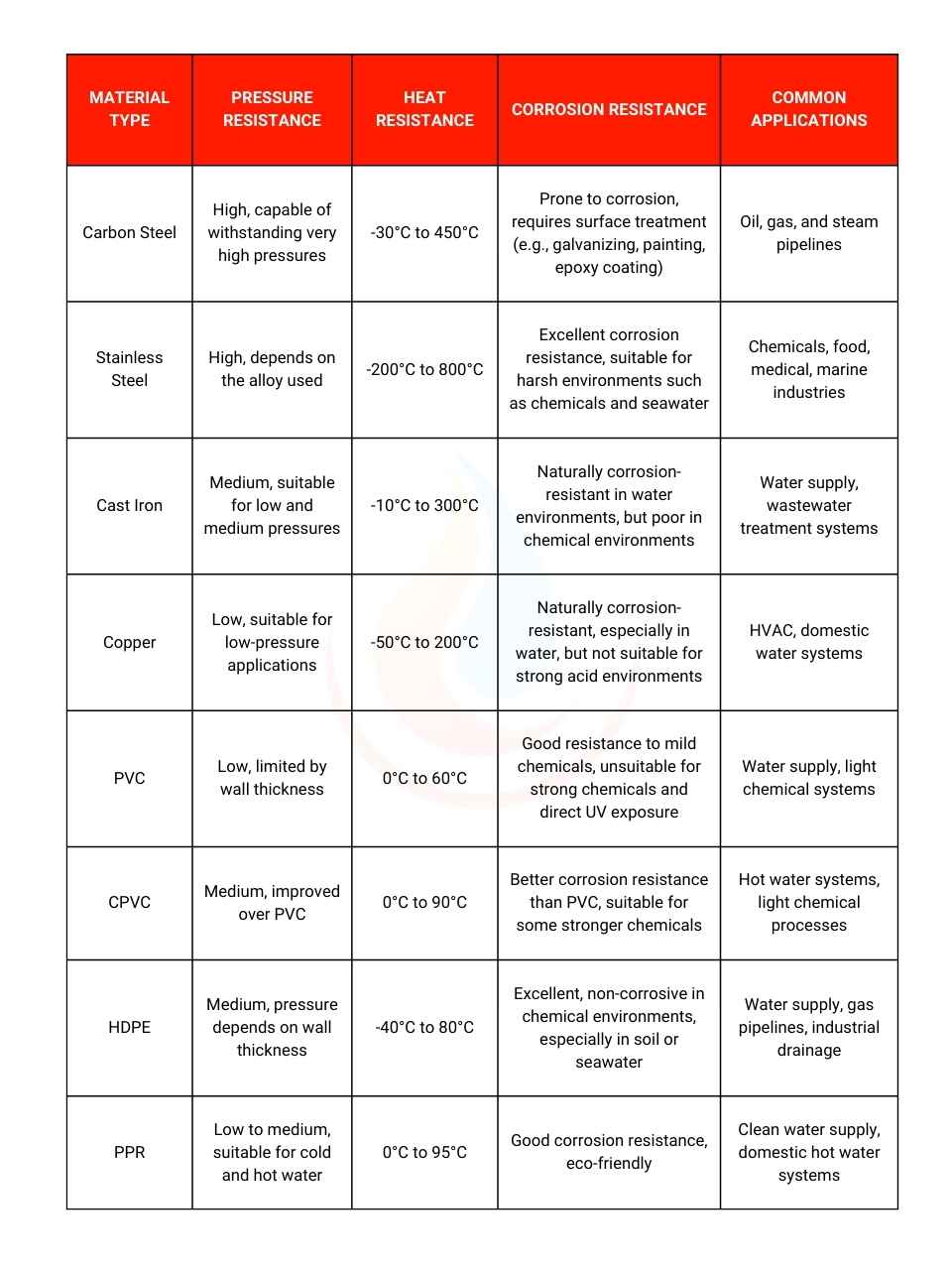
Choosing the right material for piping is a critical factor that not only determines the system’s performance and longevity but also affects pipe sizing. The mechanical and chemical properties of the material influence its ability to withstand pressure, temperature, and corrosion, directly impacting design and size decisions.

Examples:
- Hot Water Systems: A PVC pipe system might require a larger diameter due to the material’s limitations in handling high pressure and temperature. In contrast, a high-pressure gas system can utilize stainless steel pipes with thinner walls, optimizing flow without increasing pipe size.
- Liquefied Natural Gas (LNG) Systems: These demand materials that can endure extremely low temperatures, making stainless steel the optimal choice.
- Domestic Water Supply Systems: Polypropylene Random Copolymer (PPR) pipes are suitable for their cost-effectiveness and eco-friendliness.
Selecting the appropriate material ensures system performance and safety while directly influencing pipe size and cost. Understanding the properties of each material is a crucial step in optimizing the design and operation of industrial systems.
4. Working environment
The working environment is a crucial factor influencing the selection of size and material for industrial piping. These factors impact not only system performance but also its lifespan and safety.
4.1. Ambient Temperature
- Thermal Expansion:
High or low ambient temperatures can cause pipes to expand or contract, creating internal stress on the pipe walls. For example:- Metals like steel exhibit relatively low thermal expansion but require flexible joints to alleviate stress.
- Plastics such as PVC and PPR have higher thermal expansion coefficients, necessitating expansion joints or strategic installation layouts to prevent deformation.
- Material Temperature Tolerance:
Ambient temperatures can limit the application range of certain materials. For example:- PVC becomes brittle and prone to cracking in environments below 0°C.
- HDPE remains stable in low-temperature conditions, making it suitable for cold environments.
4.2. Humidity
High humidity levels promote condensation, accelerating corrosion in materials like carbon steel or cast iron without protective coatings.
- For systems frequently exposed to moisture or seawater, stainless steel or plastics like HDPE are optimal choices.
- Carbon steel or cast iron pipes should be surface-treated with epoxy coatings, anti-rust paints, or galvanization to mitigate moisture impact.
4.3. Other environmental factors
Vibrations:
In areas with heavy vibrations, such as near industrial machinery or pumps, pipes must be supported with mounts or vibration dampers to prevent mechanical damage. Metals like steel are ideal due to their high tensile strength, but welded joints or connections require regular inspections.
Impacts:
In environments with frequent physical impacts (e.g., workshops), materials like steel or HDPE offer better impact resistance than PVC or cast iron. Protective measures such as outer casings or strategic routing of pipes can enhance durability.
4.4. Integrating environmental factors into Pipe Design
When evaluating the working environment, all factors should be assessed comprehensively to choose suitable materials. Proper design from the outset minimizes the risk of damage, reduces maintenance costs, and enhances system safety.
Examples:
- In low-temperature and high-humidity environments such as cold storage plants, HDPE or stainless steel is commonly preferred.
- In high-vibration zones like chemical plants, carbon steel or stainless steel combined with specialized anti-vibration supports is recommended.
A stable and long-lasting piping system can only be achieved when all environmental factors are accurately considered during the design phase.
5. Standards and Regulations
The selection of industrial pipe sizes is influenced not only by technical factors but also by standards and regulations to ensure performance, safety, and legal compliance. National and international standards and safety regulations provide guidance for designing, manufacturing, and operating piping systems.
5.1. National and International Standards
- ASME (American Society of Mechanical Engineers):
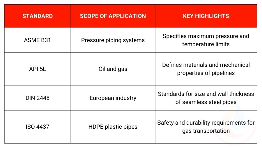
ASME B31 (Code for Pressure Piping) is one of the most widely recognized standards globally, applicable to pressure piping systems. Key criteria include:- Defining design pressure and maximum operating temperature.
- Specifying wall thickness based on material and operating pressure.
- Guidelines for strength testing and corrosion prevention.
- API (American Petroleum Institute):
API standards focus on oil and gas pipeline systems. For instance, API 5L specifies the dimensions, wall thickness, and mechanical properties of pipelines for transporting oil, gas, and water. - DIN (Deutsches Institut für Normung):
DIN standards, widely used in European industrial systems, provide guidance on materials, thickness, and pressure resistance. - ISO (International Organization for Standardization):
- ISO 9001 ensures the quality of pipe manufacturing.
- ISO 4437 applies to HDPE pipes used in gas transportation.
Compliance with these standards ensures reliable and safe system operation while meeting industry and regulatory requirements.

5.2. Safety regulations
Maximum Allowable Working Pressure (MAWP):
Defines the pressure limit that the pipe can withstand under normal operating conditions. This ensures no cracks or leaks occur that might pose safety risks. MAWP is typically calculated using the formula:
Where:
- S: Allowable stress of the material.
- t: Wall thickness of the pipe.
- D: Outside diameter of the pipe.
Minimum wall thickness:
This regulation ensures that the pipe is strong enough to withstand pressure and mechanical impacts. Standards like ASME B31.3 provide charts for minimum wall thickness based on pressure, temperature, and material.
Fire and Explosion safety:
Special regulations apply to pipeline systems carrying flammable substances or hazardous gases, requiring stringent checks for heat resistance and leak prevention.
When designing or selecting pipelines, it is essential to thoroughly reference the relevant standards and integrate them with the specific technical requirements of the project. This ensures that the system is not only efficient but also fully compliant with safety and legal requirements.

