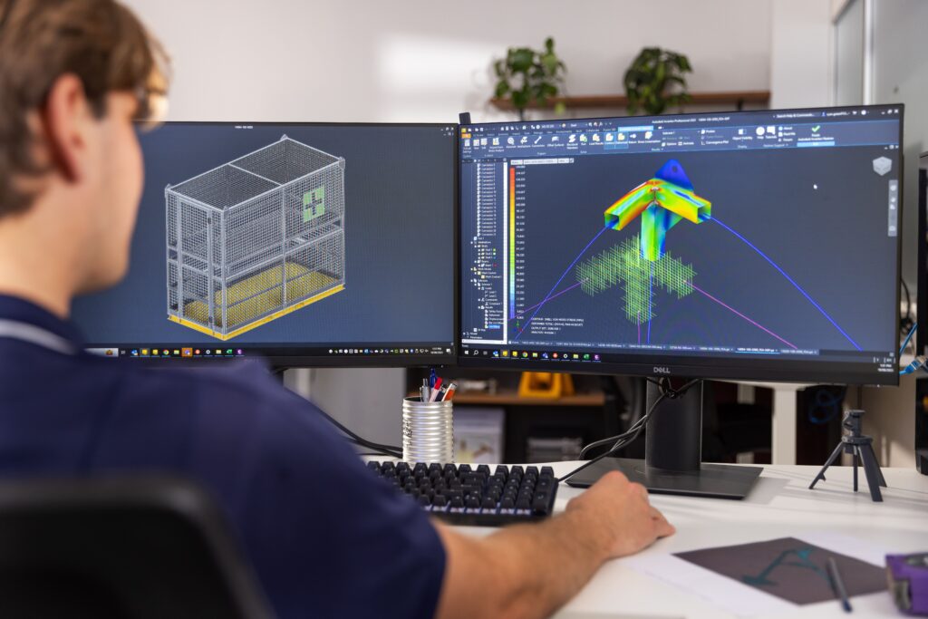
Finite Element Analysis (FEA) is extensively applied across various industries, including heavy-duty equipment such as boilers, pressure vessels, and piping systems. These structures operate under high pressure and challenging conditions, making safety and durability paramount. FEA enables engineers to accurately simulate how these components respond to stress, temperature, and other environmental factors.
In boiler design, FEA is used to assess the strength of surfaces subjected to high heat and pressure, ensuring materials can withstand thermal expansion cycles without cracking. Similarly, pressure vessels are analyzed to verify that the tank walls endure high pressure and resist corrosion. Piping systems also undergo simulation to ensure weld joints and connections maintain durability during operation.
FEA helps identify design weaknesses, optimize structural integrity, lower production costs, and enhance safety—offering effective solutions for companies in the heavy industry sector.
1. Overview of Finite Element Analysis (FEA)
1.1. Definition of FEA
Finite Element Analysis (FEA) is a computerized technique for solving complex mechanical problems in engineering design. This method divides a large structure into smaller, finite elements, analyzing how these elements behave under forces, stress, and boundary conditions. By examining interactions between these elements, FEA predicts stress, deformation, and other critical factors within a system.
1.2. The crucial role of FEA in product design processes
FEA is essential in modern product design, enabling engineers to identify potential issues before production. Through real-world condition simulations, FEA provides precise insights into product performance and durability, guiding design decisions and optimization. This not only minimizes development costs but also accelerates time-to-market.

1.3. Comparison of FEA with traditional analysis methods
Unlike traditional analysis methods, such as manual calculations or simplified modeling, Finite Element Analysis (FEA) enables the handling of complex structures with higher accuracy. Traditional methods often rely on assumptions and approximations, which can lead to significant errors in complex scenarios. FEA, however, can handle multivariable calculations and apply complex boundary conditions, providing a more detailed and comprehensive understanding of structural behavior. This capability has made FEA an essential tool in modern engineering design and structural analysis.
2. Principles of Finite Element Analysis
Finite Element Analysis (FEA) is a powerful numerical method used in engineering to simulate and predict how structures and systems respond under specific conditions. By dividing complex structures into smaller, more manageable elements, FEA allows engineers to accurately calculate factors such as material strength, stiffness, and deformation. This helps in optimizing designs and ensuring product safety.
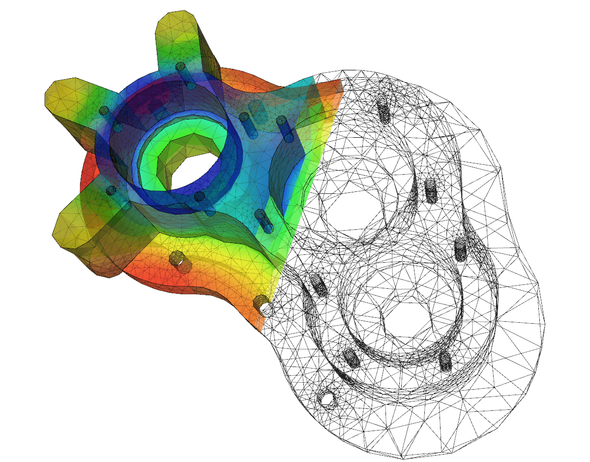
The core principle of FEA is the division of the area of interest into small elements, known as “meshing,” followed by the assembly of corresponding physical equations to solve engineering problems. Widely applied across various fields—ranging from automotive and aerospace to civil engineering—FEA enables engineers to anticipate system behavior prior to production or construction, optimizing design and reducing real-world testing costs.
Source: internet
3. Principles of Finite Element Analysis
The FEA process consists of three main stages: pre-processing, processing, and post-processing. Each stage plays a critical role in accurately simulating real-world engineering issues, delivering precise results for analysis and design.

3.1. Pre-Processing
In the pre-processing stage, engineers define the physical parameters and real-world conditions applicable to the analysis model. This includes specifying the geometry of the object, determining material properties, and setting boundary conditions.
- Geometry Definition: The object to be analyzed, such as a car frame or an aircraft wing, is geometrically defined using CAD (Computer-Aided Design) software. This model serves as the foundation for the subsequent steps in FEA.
- Material Properties: The properties of the material, such as stiffness, strength, and thermal resistance, are inputted into the system. These properties directly affect how the object responds to environmental conditions or applied loads.
- Boundary Conditions and Loads: Boundary conditions might include external factors such as force, temperature, or pressure that the object will endure throughout its operational life. Accurately defining these factors is crucial to realistically simulate what the object will experience under real-world conditions.
3.2. Processing
This stage is the core of the FEA process, where the object is divided into smaller elements, and relevant physical equations are applied.
- Meshing: The object is divided into smaller, simpler elements, such as triangular or quadrilateral shapes. These elements, along with the nodes that connect them, form a system through which physical equations are solved. Meshing is a crucial step since the granularity and accuracy of the mesh directly impact the analysis results. Areas of higher complexity require finer meshes, while simpler areas can be meshed more coarsely.
- Applying Physical Equations: After meshing, physical equations are applied to each element. These equations might involve mechanics, thermodynamics, or even electromagnetic fields, depending on the type of problem being solved.
At this stage, a system of linear algebraic equations is constructed based on fundamental physical principles, such as equations of dynamic equilibrium or thermodynamic laws. This system is then solved using numerical methods to provide insights into how the material responds under the specified conditions.
3.3. Post-Processing
The final stage of the FEA process is to analyze results and draw conclusions from the computed model.
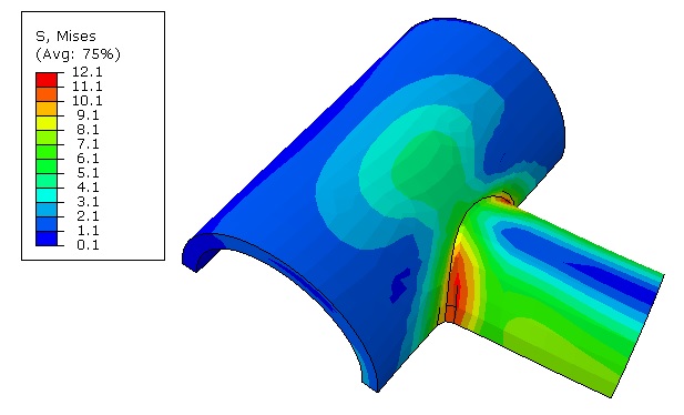
- Simulation Results: The outcomes may include charts, visualizations, or numerical data indicating variables such as deformation, stress, or temperature within the structure. Engineers use these results to identify weak points, areas of overload, or potential design flaws.
- Result Analysis: FEA results not only confirm whether the design can withstand applied loads but also aid in design optimization. Engineers can make adjustments to enhance performance or reduce weight and manufacturing costs.

If results indicate that the design does not meet requirements, engineers will return to previous steps to adjust the mesh, physical equations, or boundary conditions as needed, and then re-run the analysis process.
4. Applications of Finite Element Analysis (FEA)
4.1. Stress analysis
Identifying areas with the highest stress: FEA helps pinpoint areas with the highest stress within a structure, allowing engineers to design reinforcement measures or adjust the shape to minimize the risk of damage.
Evaluating product durability: By simulating real operational conditions, FEA provides insights into the product’s load-bearing capacity, ensuring the durability and longevity of the product.
4.2. Deformation analysis
Predicting product deformation under load: FEA enables the prediction of how a product will deform when subjected to forces, aiding in design optimization.
Checking structural load capacity: Engineers can determine if the structure has sufficient load capacity, and if necessary, make adjustments to improve stability and safety.
4.3. Thermal analysis
Calculating temperature distribution within the product: FEA can simulate the temperature distribution within a structure, helping ensure the product operates efficiently under varying temperature conditions.
Assessing heat dissipation effectiveness: Analysis helps determine if the design has sufficient heat dissipation capabilities, ensuring the safety of components and the overall performance of the product throughout operation.
4.4. Dynamic analysis
Simulating vibrations and impacts: FEA allows engineers to assess how the product will react to vibrations or impacts, ensuring stability and safety under challenging conditions.
Ensuring product stability: Analyzing dynamic issues helps verify that the product can operate stably and reliably in all real-world conditions.
4.5. Other applications
Fatigue Analysis: Evaluates the material’s resilience under repeated loads to determine the product’s lifespan.
Crack Analysis: Simulates the growth of cracks within a structure, aiding in early detection of potential serious failures.
Flow Analysis: Assesses how liquids or gases flow through structures, crucial for optimizing the performance and ensuring the safety of pipelines, tanks, and thermal equipment.
