In heavy industry, pressure equipment plays a crucial role in containing, transporting, and processing fluids under high pressure. However, one of the most significant challenges in design is complex loading conditions—a factor that directly affects the durability, safety, and lifespan of the equipment.
How can pressure equipment withstand the simultaneous effects of pressure, temperature, residual stress, and external loads without compromising structural stability? The answer lies in applying modern design methods, optimizing material selection, and adhering to strict technical standards such as ASME BPVC Section VIII, EN 13445, and API 579.
1. Complex load conditions in pressure equipment design
Complex loading in pressure equipment refers to the combination of multiple simultaneous forces, extending beyond working pressure to include mechanical, thermal, dynamic loads, and residual stresses. Unlike simple loads, complex loading is often nonlinear, time-dependent, and can lead to phenomena such as stress concentration, material fatigue, and structural instability.
Pressure equipment is subjected to various sources of load, including:
- Internal and external pressure: The primary factor generating membrane stress within the vessel walls. Excessive pressure differentials can lead to buckling or catastrophic failure if the design lacks adequate strength.
- Operating temperature: Temperature variations across different regions of the equipment can induce thermal stress, increasing the risk of cracking due to uneven expansion.
- External environmental forces: Wind loads, seismic forces, and vibrations from surrounding machinery can reduce the equipment’s load-bearing capacity.
- Residual stresses from manufacturing: Welding, cold working, or heat treatment processes can leave behind residual stresses, reducing the fatigue strength of the equipment.
One of the greatest challenges in pressure equipment design is accurately predicting the combined effects of these loads throughout the equipment’s operational life. If each load is evaluated separately without considering their interactions, localized overloading can occur, leading to premature failure.
Additionally, design standards such as ASME BPVC Section VIII and EN 13445 impose strict requirements for stress testing, fatigue analysis, and risk assessment to ensure that the equipment operates safely under real-world loading conditions.
2. Types of loads affecting pressure equipment
During operation, pressure equipment is subjected to multiple concurrent loads, which can be categorized into the following main groups:
| LOAD TYPE | CAUSE | EFFECT ON EQUIPMENT |
| Internal pressure load | Working pressure from enclosed fluids or compressed gases | Causes wall expansion, inducing tensile stress in the material |
| External pressure load | External pressure (e.g., vacuum conditions, deep-water operation) | Generates compressive stress, potentially leading to buckling failure |
| Thermal load | Material expansion or contraction due to temperature fluctuations | Induces thermal stress, potentially causing cracking or warping |
| Dynamic load | Pressure fluctuations, vortex shedding, machinery vibrations | Accelerates material fatigue, reducing equipment lifespan |
| Mechanical load | Equipment self-weight, support reactions, external forces | Creates stress concentrations at welds and contact points |
| Chemical load | Corrosion from internal fluids or external environments | Degrades material strength, leading to pitting corrosion or stress corrosion cracking |
| Environmental load | Wind, ocean waves, earthquakes, and vibrations from nearby equipment | Induces vibrations, increasing the risk of structural instability |
3. Analysis of internal and external pressure loads in pressure equipment
3.1. Internal pressure
Internal pressure is the most critical factor in pressure equipment design. As pressure increases, the induced stress in the vessel wall rises proportionally. According to Lame’s theory, the hoop stress in a cylindrical shell under internal pressure can be calculated using the following equation:

Where:
- P is the internal pressure,
- r is the mean radius of the equipment,
- t is the wall thickness of the vessel.
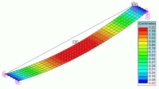
However, in vessels with complex structures or reinforcement elements such as stiffening ribs and flanges, stress concentration may occur. In such cases, detailed stress analysis using the Finite Element Analysis (FEA) method is required.
3.2. External pressure
Unlike internal pressure, external pressure acts inwards on pressure equipment, potentially leading to structural instability (buckling) if not properly designed.
As external pressure increases, the vessel shell initially undergoes elastic deformation. However, if the pressure exceeds the critical threshold, it can result in localized plastic deformation or even catastrophic collapse failure. This phenomenon is common in thin-walled vessels, vacuum chambers, and equipment operating in low-pressure environments or subjected to environmental loads such as seawater pressure or soil pressure.
According to ASME Boiler and Pressure Vessel Code (BPVC) Section VIII, Division 1, the external pressure resistance of a vessel is determined by:
- Wall thickness: Thinner walls increase the risk of buckling.
- Vessel radius: Larger-diameter vessels are more susceptible to deformation.
- Material strength: Materials with higher elastic modulus exhibit better resistance to external pressure.
- Structural reinforcement: Stiffening rings or reinforcement ribs improve the vessel’s ability to withstand external loads.
Beyond theoretical calculations, Finite Element Analysis (FEA) is often employed to precisely assess buckling risks, especially for complex-shaped vessels or those operating under severe conditions.
4. Thermal load and brittle fracture risks in pressure equipment
When temperature changes, the materials in pressure equipment expand or contract, generating thermal stress. If the temperature difference between regions within the equipment is too large (thermal gradient), the resulting stress may exceed the material’s tolerance, leading to thermal cracking. This phenomenon is particularly dangerous at weld joints or areas with stress concentration.
According to API 579-1/ASME FFS-1, equipment operating at temperatures above 400°C must undergo rigorous thermal stress analysis to prevent failures and ensure safe operation.
Examples:
- Boilers and heat exchangers can experience warping or cracking due to uneven thermal expansion.
- Low-temperature equipment (below -50°C) is prone to brittle fracture, reducing its structural integrity.
Design Solutions:
- Use high-temperature-resistant materials such as Cr-Mo alloy steel (ASTM A387, A335).
- Calculate thermal expansion coefficients to design structures that can withstand thermal stress.
- Implement expansion joints to reduce thermal stress buildup.
5. Dynamic loads and mechanical vibrations in pressure equipment
During operation, pressure equipment is subjected to not only static loads but also dynamic loads and mechanical vibrations, which can cause severe failures such as fatigue failure, dangerous resonance, and structural damage.
5.1. Causes of dynamic loads and mechanical vibrations
- Sudden pressure changes: Occur during rapid valve operations, pump activation, or pressure wave propagation in the system (water hammer).
- Vibrations from rotating machinery: Compressors, pumps, and turbines can induce forced vibrations on piping and vessel bodies.
- Flow-induced vibrations (FIV): Turbulent flow or pressure pulsations can lead to structural damage.
- Impact loads: Caused by uneven thermal expansion or external mechanical forces.
5.2. Consequences and control standards
If not properly designed and controlled, dynamic loads can shorten equipment lifespan, cause fatigue cracks, or lead to localized structural failures. Standards such as ASME BPVC Section VIII, API 579-1/ASME FFS-1, and EN 13445 provide methods for dynamic load assessment, including:
- Natural frequency analysis to avoid resonance with excitation frequencies.
- Fatigue stress analysis to ensure equipment durability.
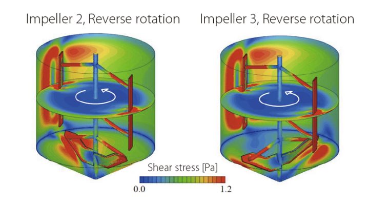
- Computational Fluid Dynamics (CFD) simulations and Finite Element Analysis (FEA) to predict flow-induced forces and pressure oscillations.
5.3. Design solutions to reduce dynamic loads
- Structural reinforcement: Use stiffening rings and minimize the unsupported length of pressure surfaces.
- Vibration damping: Implement dampers, springs, or vibration isolation techniques.
- Operational control: Adjust valve opening/closing speeds and install pressure dampers to mitigate pressure shocks.
By controlling dynamic loads, pressure equipment can operate reliably and safely throughout its service life.
6. Effects of corrosion and chemical loads in pressure equipment
Pressure equipment often operates in corrosive chemical environments or is exposed to chemical reactions, leading to material degradation, reduced lifespan, and a high risk of serious failures. Without proper design and control measures, corrosion and chemical loads can cause rapid deterioration, including brittle fractures, leaks, or even explosions.
6.1. Types of corrosion in pressure equipment
Uniform Corrosion
This is the most common type, where the entire metal surface is uniformly attacked by the chemical environment. Corrosion rates can be predicted and controlled using standards like API 571 or NACE MR0175.
Localized Corrosion
Occurs at specific locations, forming pitting corrosion or crevice corrosion. These vulnerable areas are commonly found at joints, weld edges, or interfaces between different materials.
Galvanic Corrosion
Happens when two dissimilar metals with different electrochemical potentials are in contact within a conductive environment, forming a galvanic cell. One metal corrodes faster than it would independently.
Stress Corrosion Cracking (SCC)
When materials are subjected to tensile stress in a corrosive environment, cracks can develop without visible warning signs. Stainless steel alloys exposed to chloride ions are particularly vulnerable to SCC.
Flow-Accelerated Corrosion (FAC)
Occurs when fluid velocity removes the protective oxide layer on the metal surface, accelerating corrosion rates. This phenomenon is common in piping, heat exchangers, and high-velocity flow systems.
In addition to corrosion mechanisms, some chemical reactions can alter the mechanical properties of materials, reducing the load-bearing capacity of pressure equipment:
- Hydrogen Embrittlement (HE): When hydrogen diffuses into metals, it can cause brittleness and cracking. This is particularly dangerous for equipment operating in hydrogen-rich environments or undergoing electrochemical reactions.
- High-Temperature Oxidation: Equipment operating in oxidizing atmospheres at elevated temperatures can develop oxide layers, weakening the mechanical strength and increasing the risk of metal spallation.
- Medium-Material Reactions: Some process fluids react with metal surfaces, forming compounds that weaken the material. For example:
- H₂S exposure can cause Hydrogen-Induced Cracking (HIC).
- Ammonia (NH₃) can lead to Alkaline Stress Corrosion Cracking (ASCC).
6.2. Design solutions to minimize corrosion and chemical load effects
- Selecting appropriate materials: Use stainless steel, nickel alloys, or corrosion-resistant materials to extend equipment lifespan.
- Surface protection: Apply epoxy coatings, chemical-resistant liners, or corrosion-resistant metal cladding to protect surfaces from aggressive media.
- Controlling the operating environment: Remove corrosive impurities, maintain pH balance, and regulate oxygen concentration to minimize material degradation.
- Reducing stress concentration: Avoid tight crevices, optimize weld designs, and eliminate sharp edges to reduce localized corrosion risks.
- Regular inspections: Utilize non-destructive testing (NDT) methods such as ultrasonic testing (UT), magnetic particle inspection (MPI), or eddy current testing (ECT) to detect early signs of corrosion and cracking.
By implementing proper material selection, design enhancements, environmental control, and regular inspections, pressure equipment can maintain structural integrity and operate safely over its designed lifespan.
7. Environmental loads and their impact on pressure equipment
Pressure equipment is not only subjected to operational loads but also exposed to external environmental factors such as temperature fluctuations, humidity, wind, seismic activity, and solar radiation. These factors can degrade material strength, induce additional stress, and shorten the equipment’s service life. Without proper design considerations and protective measures, environmental impacts can significantly increase the risk of failure or safety hazards during operation.
7.1. Ambient temperature
Pressure equipment operating in environments with large temperature variations may experience cyclic thermal expansion and contraction, leading to thermal fatigue. In extremely low-temperature conditions (below -50°C), materials can become brittle and prone to cracking due to brittle fracture. Standards such as ASME BPVC Section VIII provide guidelines on temperature limits and material selection to ensure ductility under harsh conditions..
7.2. Humidity and condensation
High humidity or frequent temperature changes can cause condensation on the equipment’s surface, increasing the risk of corrosion. This is especially critical for outdoor installations or equipment operating in marine environments. Protective solutions such as anti-corrosion coatings, stainless steel materials, and proper drainage system designs are essential to mitigate moisture-related degradation.
7.3. Wind and storm impact
Outdoor pressure equipment, particularly storage tanks, distillation columns, and tall structures, must withstand high wind loads. Strong winds can induce vibrations, cause fatigue stress, and compromise structural stability. The ASCE 7-22 standard outlines wind load calculations and structural reinforcement requirements to enhance equipment resilience against wind forces.
7.4. Seismic loads and vibrations
Seismic events can impose substantial lateral forces on pressure equipment, especially large storage tanks and pipeline systems. Equipment that is not designed for seismic loads may topple, crack, or develop hazardous leaks. ASME BPVC Section VIII and API 650 provide methodologies for seismic load calculations and reinforcement techniques to improve earthquake resistance.
7.5. Solar radiation and material aging
Pressure equipment exposed to prolonged solar radiation may experience thermal degradation, reducing mechanical properties over time. For non-metallic components such as polymer linings and gaskets, UV exposure can significantly weaken structural integrity. The ASTM G154 standard specifies testing methods to evaluate material resistance to UV-induced aging.
7.6. Design solutions to mitigate environmental load effects
- Selecting temperature-resistant materials: Using low-temperature-resistant alloys (e.g., ASTM A333 for cryogenic applications) and heat-resistant alloys (e.g., ASTM A387 for high-temperature operations) ensures optimal performance in extreme conditions.
- Corrosion protection and surface treatment: Applying anti-corrosion coatings, thermal insulation, or specialized surface treatments minimizes the impact of moisture and salt exposure.
- Structural reinforcement for wind and seismic loads: Implementing anchoring systems, reinforcement rings, or additional support structures in compliance with ASCE 7-22 and API 650 enhances resistance to environmental forces.
- Regular inspection and maintenance: Utilizing non-destructive testing (NDT) methods such as ultrasonic testing (UT) and magnetic particle inspection (MPI) enables early detection of environment-induced damage.
- Optimal equipment placement: Positioning equipment in orientations that reduce wind exposure and solar radiation while incorporating protective shielding improves long-term durability.
Learn more about the allowable stress