A heat exchanger is a critical device in various industrial sectors, enabling efficient thermal energy transfer between two fluid streams without mixing them. In this article, we will explore what a heat exchanger is, its working principles, common types, and real-world applications to better understand its essential role in process efficiency and energy conservation.
1. Definition of a heat exchanger
A heat exchanger is a device designed to transfer heat between two flowing fluids through convection and conduction, without direct contact. It is widely used in petrochemical, chemical processing, and food equipment industries.
Heat exchangers serve two primary purposes:
- To recover thermal energy from hot process streams for reuse.
- To control chemical reactions by maintaining specific temperature conditions within a system.
All heat exchangers operate based on fundamental thermodynamic laws and heat transfer mechanisms, which govern how thermal energy is transmitted on a macroscopic scale. In a typical heat exchanger, three main elements interact: A hot fluid; A cold fluid; And a solid heat transfer surface (wall or partition) that separates them. Heat is transferred from the hot fluid, through the wall, to the cold fluid.
Understanding the following thermodynamic principles is key to grasping how heat exchangers function:
1.1. First law of thermodynamics (Law of energy conservation)
This law states that energy—whether in the form of heat or work—cannot be created or destroyed, only transferred between systems or transformed from one form to another. In a heat exchanger, this principle is expressed through the energy balance equation:
(Heat In) + (Heat Generated) = (Heat Out) + (Heat Accumulated)
This equation ensures that all energy entering and leaving the system is accounted for.
1.2. Second law of thermodynamics
This law introduces the concept of entropy—a measure of disorder within a system. It states that the entropy of the universe tends to increase, and energy transfer occurs in the direction that increases entropy. Specifically, heat always flows from a higher temperature zone to a lower temperature zone.
In the context of a heat exchanger:
The cold fluid absorbs heat, increasing its temperature.
The hot fluid loses heat, decreasing its temperature.
1.3. Heat transfer mechanisms
Heat transfer within a heat exchanger occurs through a combination of conduction (through solid materials), and convection (between fluids and the heat transfer surface).
The primary driving force behind heat transfer is the temperature differential between the inlet and outlet streams and across the wall.
Approach Temperature: Every heat exchanger has a minimum approach temperature suitable for its intended application. Misjudging this parameter may result in selecting an exchanger that fails to meet process performance requirements.
Conduction: The direct transfer of thermal energy through a solid medium, driven by the kinetic interaction between molecules. In a heat exchanger, conduction occurs across the heat transfer surface that separates the two fluids.
Convection: The transfer of heat through fluid motion along the wall surface. Governed by Newton’s Law of Cooling, which states that the rate of heat transfer is proportional to the temperature difference between the surface and the adjacent fluid.
1.4. Sequence of heat transfer in an exchanger
In a heat exchanger with a solid partition wall, the heat transfer process follows this sequence:
Hot fluid → hot-side surface of the wall (via convection)
Through the wall (via conduction)
Wall → cold fluid (via convection)
This layered process ensures the efficient and controlled transfer of energy between process streams without contamination or loss of fluid integrity.
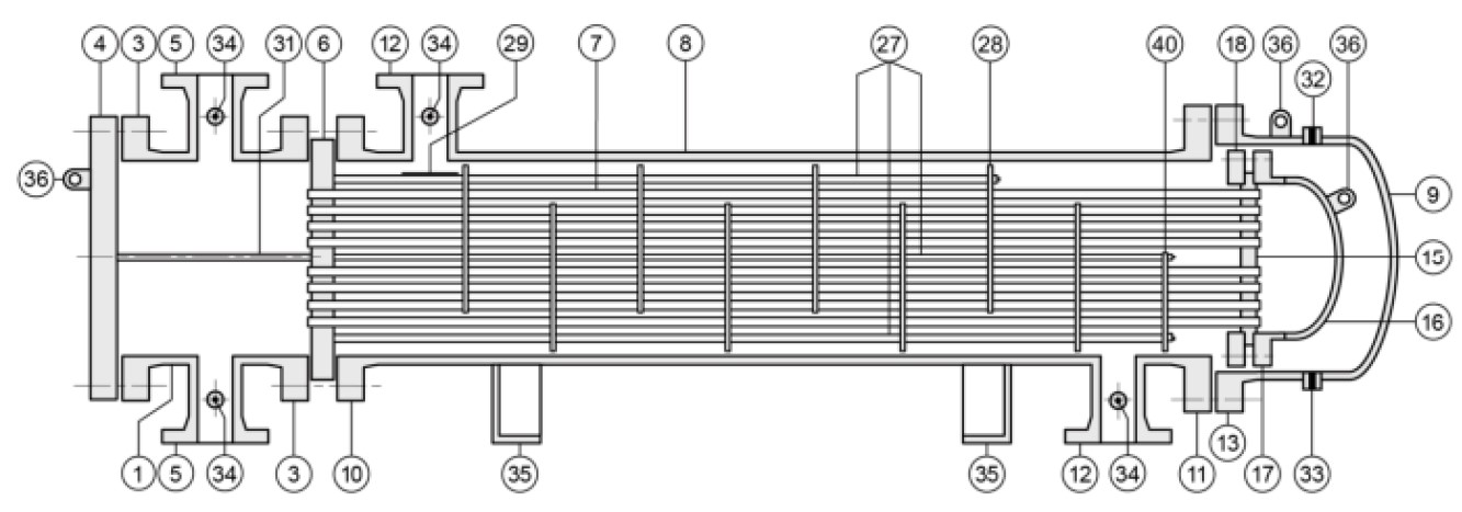
2. Main components and constituent parts of the heat exchanger
| No. | Component | No. | Component |
|---|---|---|---|
| 1 | Stationary Head – Channel | 21 | Floating Head Cover – External |
| 2 | Stationary Head – Bonnet | 22 | Floating Tubesheet Skirt |
| 3 | Stationary Head Flange – Channel/Bonnet | 23 | Packing Box |
| 4 | Channel Cover | 24 | Packing |
| 5 | Stationary Head Nozzle | 25 | Packing Gland |
| 6 | Stationary Tubesheet | 26 | Lantern Ring |
| 7 | Tubes | 27 | Tierods and Spacers |
| 8 | Shell | 28 | Transverse Baffles or Support Plates |
| 9 | Shell Cover | 29 | Impingement Plate |
| 10 | Shell Flange – Stationary Head End | 30 | Longitudinal Baffle |
| 11 | Shell Flange – Rear Head End | 31 | Pass Partition |
| 12 | Shell Nozzle | 32 | Vent Connection |
| 13 | Shell Cover Flange | 33 | Drain Connection |
| 14 | Expansion Joint | 34 | Instrument Connection |
| 15 | Floating Tubesheet | 35 | Support Saddle |
| 16 | Floating Head Cover | 36 | Lifting Lug |
| 17 | Floating Head Cover Flange | 37 | Support Bracket |
| 18 | Floating Head Backing Device | 38 | Weir |
| 19 | Split Shear Ring | 39 | Liquid Level Connection |
| 20 | Slip-on Backing Flange | 40 | Floating Head Support |
The illustration below shows typical parts and connection details of a heat exchanger, with each part numbered according to the table above.
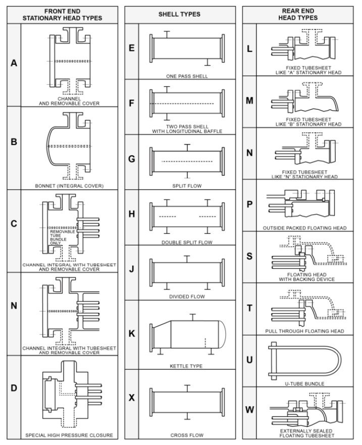
3. Guidelines for selecting a type of heat exchanger
There are various configurations of shell and tube heat exchangers, each with its own advantages and disadvantages depending on factors such as process and thermal requirements, installation space, investment budget, fouling tendency, and cleaning needs. This section provides information on some of the most common configurations and briefly discusses the considerations when planning and selecting a heat exchanger configuration.
3.1. Straight tube, fixed tube sheet type heat exchangers
Straight tube, fixed tubesheet heat exchangers are typically the lowest-cost type among shell and tube designs. Common examples include BEM, AEL, and NEN types. Advantages include low cost and easy access to the tube side for cleaning.
However, since the tube bundle is non-removable, mechanical cleaning of the shell side is not possible. This may be problematic if the shell-side fluid tends to cause fouling or sediment buildup.
Another disadvantage is that the fixed tubesheet structure can lead to thermal expansion stress due to the differential expansion between the shell and the tubes. In such cases, an expansion joint may be required to reduce stress, which increases cost and introduces an additional potential point of failure.
NEN and AEL types use bolted end covers, offering the additional benefit of tube-side cleaning without removing the cover or disconnecting inlet/outlet piping—saving time for frequent maintenance.
3.2. Expansion joint considerations
In any shell and tube heat exchanger, the operating fluid temperature causes different thermal expansions along the shell and tube materials, and this difference varies along the length of the equipment. While the tube material is exposed to fluids on both sides, the shell material only contacts the shell-side fluid. Therefore, thermal expansion differs between shell and tubes, especially if they are made from different materials.
For fixed tubesheet exchangers, this uneven thermal expansion results in stress on the shell, tubes, and tube sheets, which must be carefully calculated during design. An expansion joint may be necessary to alleviate this stress, especially in cases with significant temperature differences between the shell side and tube side.
For this reason, designers must be aware of the expected operating temperatures of the fluids on both sides, including temporary or special conditions. Situations to consider include: startup, shutdown, steady-state operation, external piping loads, and abnormal conditions such as malfunctions or steam cleaning.
Any existing fixed tubesheet heat exchanger must be re-evaluated before being operated under a new thermal condition.
There are currently two main types of expansion joints:
Flexible Shell Element (FSE): A thick-wall expansion joint design. Though less flexible than bellows, FSEs are significantly more durable and less prone to damage. Multiple FSEs can be connected in series to increase expansion capacity.
Bellows: Commonly used in exchangers subject to large thermal expansion differentials. Bellows have thin walls and one or more convolutions allowing movement but are more vulnerable to mechanical damage. Therefore, they are typically protected by a shroud.
3.3. Removable U-Type tube bundle heat exchangers
BEU, BKU, and AEU types are typical examples of heat exchangers with removable U-tube bundles. These are cost-effective configurations and offer better access to the shell side for inspection and cleaning compared to fixed types.
A major advantage of the U-tube configuration is its inherent flexibility in thermal expansion; the tube bundle can expand and contract with temperature changes without imposing stress on the shell. Individual tubes or portions of the bundle can expand at varying levels without adverse effects. No expansion joint is needed for this type.
Additionally, the tube bundle can be replaced easily when necessary.
However, a disadvantage is the difficulty of cleaning the curved (bend radius) portions of the U-tubes. Furthermore, individual tubes within the bundle cannot be replaced if damaged.
3.4. Floating tubesheet types
Heat exchangers with rear-end types P, S, T, and W all use floating tubesheets. This design allows the tube bundle to thermally expand freely and be removable, similar to U-tube types, while maintaining the advantage of straight tubes.
In these designs, expansion joints are generally not required since the tube bundle can expand freely with temperature changes. An exception may apply to one-pass designs of S and T types, where the use of expansion joints might need to be considered.
Because both the shell side and tube side are accessible for cleaning, floating tubesheet designs are often used in applications involving dirty fluids, such as in refineries. Tube bundles are also relatively easy to replace.
However, each floating tubesheet type has different design characteristics, and overall, this type tends to be more expensive to fabricate compared to fixed tubesheet or U-tube designs.
P and W type exchangers have the disadvantage of requiring packing seals, which are generally less durable than gasket seals and may impact the long-term reliability of the equipment.
Meanwhile, S and T designs use bolted connections immersed in the process fluid, which introduces the risk of cross-contamination between shell-side and tube-side fluids if a leak occurs at the gasketed seal.
3.5. Double tubesheet designs
Most shell and tube heat exchanger configurations can be manufactured with double tubesheets. This design incorporates an additional (secondary) tubesheet and a sealing ring to enhance the isolation between the shell and tube sides of the exchanger.
If a leak occurs at the tube-to-primary-tubesheet weld, the leakage is contained within a separate cavity or is discharged externally before it can reach the opposite side. Although this configuration significantly increases equipment cost, it minimizes the risk of cross-contamination between the two process fluids—an important advantage in applications requiring high safety standards or strict process control.
Therefore, in situations where leakage between the shell-side and tube-side fluids is unacceptable, the use of double tubesheet designs should be prioritized.
3.6. Shell Configurations
The simplest, most common, and usually least expensive shell configuration is the TEMA Type E (straight-through shell), where the shell-side fluid flows in a single pass from one end to the other.
Type F uses a longitudinal baffle to create a two-pass shell-side flow. This design is useful in cases of temperature cross—e.g., when the cold fluid outlet temperature is higher than the hot fluid outlet temperature.
Note: The longitudinal baffle can be either welded directly to the shell or mounted on the tube bundle with a flexible gasketed seal at the shell wall.
Types G and H use a center baffle to divide the shell-side flow into two sections and are typically used in thermosyphon reboilers.
K-type (kettle-type) shells have a larger diameter to form a vapor disengagement space above the tube bundle and are also commonly used in reboiler applications.
J and X types offer additional options for divided flow or cross-flow arrangements on the shell side.