In boiler design and manufacturing, fittings, accessories, and control devices play a crucial role in ensuring safe and efficient operation. From boiler nameplates, safety valves, and gauge glasses to water level controls, each component serves a specific function—maintaining pressure, regulating water levels, and protecting the system from overload or damage.
Understanding and selecting the right mountings not only extend the boiler’s lifespan but also optimize the overall system’s efficiency.
1. Boiler Nameplate
In the late 19th century, boiler explosions were a frequent occurrence. To mitigate these risks, a company was established in Manchester to conduct independent boiler inspections. This organization later evolved into The Safety Assessment Federation (SAFed), which now oversees the approval of boiler equipment and control valves in the UK.
The early success of this inspection system was remarkable: only 8 out of 11,000 inspected boilers exploded, compared to 260 explosions among uninspected boilers. This outcome contributed to the passage of the Boiler Explosions Act (1882), which mandated that all boilers must have a nameplate.
Functions of the Nameplate
- Serial and model number: Helps uniquely identify the boiler for spare part procurement and operational history tracking.
- Boiler capacity: Can be expressed in various ways, as discussed in previous modules.
2. Safety valves
Safety valves are critical components in a boiler system, designed to automatically release excess pressure when it exceeds the allowable limit. When the pressure reaches the set threshold, the valve spring compresses, opening the valve to vent steam, thereby maintaining a safe operating pressure and preventing explosions.
Safety Valve Standards
- Europe: EN 12953
- United States and other regions: ASME and national standards
Basic Requirements
- The minimum discharge capacity must handle the full live steam output.
- Safety valves must not operate at pressures exceeding 110% of the design pressure.
- The minimum inlet diameter should be 20 mm.
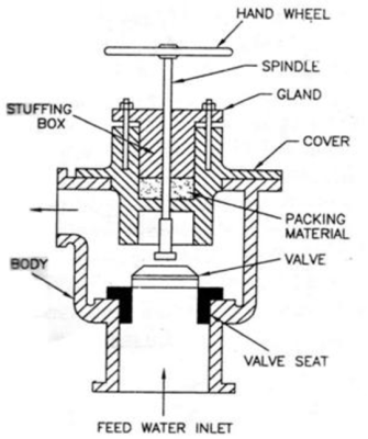
3. Boiler stop valves
Also known as the crown valve, the boiler stop valve serves as an isolation device, controlling the flow of steam from the boiler to the steam distribution system. It plays a key role in system safety, preventing overpressure conditions and unintended steam leaks.
Materials
Historically, boiler stop valves were made of grey cast iron. However, for high-pressure applications, materials such as steel and brass are used for enhanced durability.
According to BS 2790 (gradually being replaced by EN 12953), grey cast iron is no longer permitted for boiler stop valves in steam boilers. Spheroidal graphite iron (SG iron), which has mechanical properties similar to steel, is now commonly used by manufacturers for standard boiler stop valves.
Operating Principles and Requirements
- Boiler stop valves are not designed for throttling (flow regulation). Instead, they should be either fully open or fully closed.
- When opening the valve, it should be done gradually to prevent water hammer, which can lead to pressure surges and priming in the boiler.
- In compliance with UK regulations, the valve should have a rising handwheel design, where the handwheel moves upward when opening, allowing operators to visually confirm the valve’s status from the ground.
- Some designs include a valve position indicator for remote monitoring.
Application in Multi-Boiler systems
When multiple boilers operate in parallel, an additional isolation valve is required in series with the boiler stop valve.
- At least one of these two valves must be lockable in the closed position to ensure safe maintenance or boiler isolation.
- The additional valve is typically a globe valve (screw-down non-return type), preventing pressure from one boiler from affecting another.
- An alternative approach is using a screw-down valve combined with a disc check valve, positioned between the flanges of the boiler stop valve and the screw-down valve.
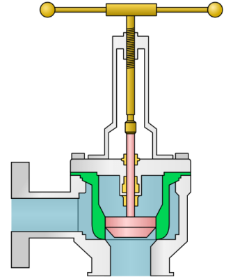
4. Feedwater check valves
The feedwater check valve is installed on the boiler feedwater line, between the feed pump and the boiler. A boiler feed stop valve is also fitted at the boiler shell to regulate the flow of water entering the system.
Operating Principle
- When the boiler is not under pressure, the check valve contains a spring with a force equivalent to the hydrostatic pressure from the elevated feedwater tank. This prevents uncontrolled water flow from the tank into the boiler due to static pressure.
- When the feed pump is in operation, its pressure overcomes the spring force, opening the valve and allowing water to flow into the boiler.
- When the pump stops, pressure drops, and the spring automatically pushes the valve shut to prevent water from flowing back from the boiler into the feed line.
- Under normal operating conditions, the valve functions as a one-way check valve, ensuring no backflow of water into the feed line when the pump is inactive.
Technical Requirements
- The valve must provide high sealing integrity to prevent water leakage.
- Operating temperatures are typically below 100°C, making soft-seal EPDM (Ethylene Propylene Diene Monomer) gaskets a suitable choice for durability and tight sealing.
- The nominal diameter (DN) of the valve must be appropriately selected to match the required feedwater flow rate, ensuring sufficient water supply to the boiler under maximum load conditions.
5. TDS Control (Total Dissolved Solids)
The TDS control system plays a crucial role in maintaining the concentration of total dissolved solids (TDS) in boiler water within permissible limits. This process, also known as continuous blowdown, helps regulate water quality and prevent scale buildup inside the boiler.
Typically, the TDS control system is connected to the boiler through a pipeline with a nominal diameter of DN15 or DN20. Monitoring can be conducted manually or automatically:
- In manual systems, the boiler operator collects a water sample during each shift, measures the TDS level, and adjusts the blowdown rate accordingly by discharging excess water when necessary.
- In automated systems, sensors continuously measure the TDS concentration, compare it to preset values, and automatically control the blowdown process, ensuring TDS levels remain within safe limits.
Operating Principle
This system operates based on the dilution principle:
- When TDS levels exceed the set threshold, a portion of the high-TDS water is discharged.
- Fresh feedwater with a lower TDS concentration replaces the discharged water, keeping the overall TDS level within an acceptable range.
This process prevents excessive scale formation, enhances heat transfer efficiency, and prolongs boiler service life.
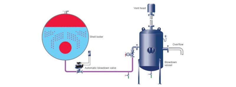
6. Bottom blowdown
Bottom blowdown is the process of removing sludge and sediment accumulated at the bottom of the boiler to prevent scale formation and maintain heat transfer efficiency. If not regularly discharged, these impurities can cause localized overheating and reduce the lifespan of boiler components.
Blowdown System & Operation
- The bottom blowdown system typically uses a manual blowdown valve, commonly sized between DN25 and DN50.
- In standard operation, this valve is opened for approximately 5 seconds per shift to remove settled impurities.
- In addition to manual blowdown, an automated blowdown system can be implemented using time-controlled valves or water quality sensors, optimizing the process and reducing operator intervention.

Depending on the boiler system design, bottom blowdown can be performed using two methods:
- Continuous Blowdown – A small, controlled flow is discharged continuously to maintain boiler water quality.
- Intermittent Blowdown – A larger volume of water is discharged at specific intervals to remove accumulated sludge and impurities.
Applying the appropriate blowdown method ensures optimal boiler efficiency and prolongs the lifespan of the equipment.
7. Pressure gauge
A pressure gauge is a mandatory device in all boiler systems, serving the function of measuring and displaying operating pressure to ensure operation within safe limits. According to EN 12953 standards, a boiler pressure gauge must have a minimum dial diameter of 150 mm for easy observation and is typically of the Bourdon tube type, operating based on the expansion principle when pressure changes.
The gauge dial is clearly marked with critical information, including normal operating pressure and the maximum allowable pressure as per the design. To protect the measuring mechanism from high temperatures, the pressure gauge is connected to the steam space of the boiler through a siphon tube containing condensate water, which helps reduce temperature before the pressure acts on the measuring element.
In addition to being installed on the boiler body, pressure gauges are also used in related systems such as blowdown tanks and steam pipelines. In these cases, the gauge dial may be smaller but must still ensure accuracy and high-pressure resistance.
8. Water level gauge glass
In a boiler system, the water level gauge glass plays a crucial role in monitoring and controlling water levels to ensure safe operation. According to EN 12953 standards, boilers with a capacity of 100 kW or more must be equipped with at least two water level gauge glasses.
8.1. Function and operating principle
The water level gauge glass allows operators to directly observe the water level inside the boiler under all operating conditions. Installation must ensure that the lowest visible water level on the gauge glass is at least 50 mm above the point where overheating risk exists. To enhance safety, the gauge glass is usually protected by a shield to minimize breakage risks while maintaining clear visibility.
During operation, the gauge glass may become damaged due to various factors, including chemical corrosion from boiler water or erosion from blowdown processes, especially at the steam interface. When signs of corrosion or erosion appear, replacing the gauge glass is necessary to maintain accuracy and operational safety.
8.2. Water level gauge glass inspection procedure
To ensure stable operation, the gauge glass must be regularly inspected to detect blockages or incorrect water level indications. The inspection process includes:
1. Checking the water connection:
- Close the water supply valve.
- Open the drain valve for about 5 seconds to check the drainage ability.
- Close the drain valve, then reopen the water supply valve.
- Observe the water level: If the water does not quickly return to the normal level, the water supply valve may be blocked and requires immediate attention.
2. Checking the steam connection:
- Close the steam valve.
- Open the drain valve for 5 seconds to check the steam passage.
- Close the drain valve, then reopen the steam valve.
- Observe the water reaction: If the water does not quickly return to normal, the steam passage may be clogged and needs inspection and correction.
Operators are responsible for checking the gauge glass at least once a day. During the inspection, appropriate personal protective equipment, such as heat-resistant gloves and safety glasses, should be worn to prevent burn risks.
8.3. Maintenance and Replacement
The gauge glass must be cleaned regularly to ensure clear visibility. When cleaning or removing the gauge glass, the following steps must be followed:
- Ensure the boiler water level is within a safe range before proceeding.
- Close the steam and water supply valves before removing the gauge glass.
- After cleaning or replacing, check the system to ensure proper operation.
The gauge glass inspection and maintenance should also be included in the annual boiler maintenance schedule. If sealing gaskets become hardened, valves are stuck, or handwheels are bent, affecting their ability to open and close, these components must be replaced immediately.
8.4. Common issues and Troubleshooting
Several common issues may arise with the gauge glass during operation, including:
- Discoloration of the glass: Caused by boiler water conditions; replace the glass if visibility is significantly reduced.
- Erosion or corrosion: If the glass becomes thin or weakened, it must be replaced for safety reasons.
- Incorrect water level display: If the steam passage is blocked, the water level may appear higher than actual. If the water passage is blocked, the gauge glass may show a fixed water level that does not reflect the actual boiler water level.
Since the gauge glass is the only direct visual indicator of the boiler water level, frequent monitoring and maintenance are mandatory. If any abnormalities in the water level display are detected, an immediate inspection should be conducted, and boiler operation should be halted if necessary to prevent overheating or severe damage.
9. Water level control system in boiler design and manufacturing
Maintaining an accurate water level in a boiler is a critical factor determining operational efficiency and system safety. The process of water level sensing and control in boilers is a complex topic, regulated by numerous stringent technical standards.
9.1. External level control chambers in boiler manufacturing
External level control chambers are components installed separately from the boiler body, designed to house water level control devices or alarms in case of operational anomalies. These chambers are typically designed according to safety standards and tailored to different types of boilers.
The water level control or alarm system is tested daily through a sequencing purge valve. When the handwheel is turned counterclockwise to the fully open position, the valve remains in normal operation mode while closing the drain path to prevent leakage.
Some handwheels feature an indicator dial for easy identification of the operating state, while others use a mechanical locking mechanism to ensure precise operation.
9.2. Water level control system inspection procedure
When the boiler is operating under normal pressure and the burner is active, the system can be inspected through the following steps:
1. Draining water from the external level chamber:
- Slowly turn the handwheel clockwise to the first stop position.
- At this point, the connection between the float chamber and the steam line is blocked, and the drain path opens, allowing water to be expelled.
- Maintain this state for approximately 5–8 seconds to ensure complete drainage.
2. Draining steam from the external level chamber:
- Continue turning the handwheel clockwise to the end of its travel.
- At this stage, the water path is completely closed, the drain valve remains open, and the float chamber and steam line are purged.
- As the boiler water level drops, the control system will activate the feedwater pump, while an alarm or burner shutdown mechanism will engage.
- If the system includes an extra low water alarm, the boiler will automatically shut down to prevent overheating risks.
- Maintain this state for 5–8 seconds to ensure complete steam purging.
3. Restoring normal operation: Turn the handwheel counterclockwise back to the initial position to close the drain path and return the system to normal operation.
9.3. Importance of regular inspection
Sequencing purge valves are manufactured by various suppliers and may differ in operation. Therefore, boiler operators must strictly follow the manufacturer’s guidelines when performing system inspections.
Daily water level inspections not only help detect issues such as blocked water passages, ineffective steam drainage, or faulty sensors but also ensure stable system operation, minimize boiler failure risks, and extend equipment lifespan.
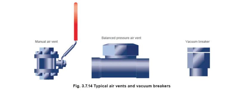
10. Air Vent and Vacuum Breaker Valves
When a boiler starts up from a cold state, the steam chamber inside is filled with air. This air has no thermal value and can negatively impact the efficiency of the steam system by creating an insulating layer on heat exchange surfaces. If not completely removed, trapped air can also cause corrosion in the condensate system.
Air within the steam chamber can be expelled through a simple air vent valve. Typically, this valve remains open until the boiler pressure reaches approximately 0.5 bar.
An alternative solution is to use a pressure-balanced air vent valve, which eliminates the need for manual air purging and ensures automatic air removal. This type of valve offers higher precision and can effectively eliminate accumulated gases inside the boiler.
Source: spiraxsarco.com
When the boiler shuts down, the steam inside the chamber condenses, creating a vacuum. This phenomenon causes external atmospheric pressure to act on the boiler shell, potentially leading to leaks at inspection doors, deformation of flat plates, and an increased risk of overfilling the idle boiler.
To prevent this, a vacuum breaker valve is installed on the boiler shell to balance pressure and protect the structural integrity of the equipment.
Learn more>>> Essential Parts of a Boiler and Their Functions
Translated and referenced from: https://www.spiraxsarco.com/learn-about-steam/the-boiler-house/boiler-fittings-and-mountings?sc_lang=en-GB