


Explore the iron oxide redox cycle, Gas Storage Vessel configuration, and key engineering considerations for high-temperature service, including creep resistance and thermal fatigue, at operating temperatures up to 900°C.
1. Gas Storage Vessels Using Chemical Reactions: An Emerging Approach to Energy Storage
In next-generation industrial energy systems, gas storage involves more than vessel capacity and pressure containment. For gases with low volumetric density under ambient conditions, particularly hydrogen (H₂), the storage method directly affects transportation efficiency, energy utilization, and overall system safety.
According to the U.S. Department of Energy (DOE), hydrogen has a high gravimetric energy density, but its low volumetric density under ambient conditions presents significant challenges for achieving compact storage. Established methods include high-pressure gas compression, cryogenic liquefaction, and materials-based storage.
While conventional methods rely on elevated pressure or specialized temperature conditions to store hydrogen, chemical reaction-based technologies offer an alternative approach by enabling controlled conversion between gas and solid materials.
One notable mechanism is the iron–iron oxide redox cycle. In this process, iron-based materials react with hydrogen or steam, undergoing chemical transformations between different material states. This mechanism enables hydrogen storage and release to be integrated into a dedicated thermochemical reaction system.
A Gas Storage Vessel employing this mechanism must therefore serve more than a containment function. Its design must also address heat transfer, structural integrity, leak tightness, and cyclic operating conditions.
At temperatures up to 900°C, these requirements become considerably more demanding. Long-term load-bearing capacity, creep deformation, thermal fatigue, and interactions between structural components must be evaluated together to ensure reliability throughout the intended service life.
These are among the key engineering challenges addressed by PREBECC in its recent design consultancy work involving high-temperature reaction systems.
2. Chemical Principles: the Iron–Iron Oxide Cycle
2.1. Why Consider Chemical Reaction-Based Storage?
At ambient temperature and pressure, hydrogen exists as H₂ molecules with low volumetric density. Storing substantial quantities within a limited space typically requires high-pressure vessels or cryogenic storage systems.
According to the DOE, compressed hydrogen storage systems commonly operate at approximately 350–700 bar, while liquid hydrogen requires temperatures near its boiling point of −252.8°C at atmospheric pressure. These conditions introduce additional challenges in pressure-vessel design, thermal insulation, auxiliary equipment, and operational control.
Materials-based storage, by contrast, relies on the chemical or physical interaction between hydrogen and a storage medium. The DOE identifies several major technology categories, including metal hydrides, adsorbent materials, and chemical hydrogen storage materials.
In the iron–iron oxide cycle considered here, the mechanism is based on a redox reaction. Rather than retaining hydrogen exclusively as compressed gas throughout the storage cycle, the system uses hydrogen to reduce iron oxide, producing metallic iron and water. Steam can subsequently react with the iron to regenerate hydrogen.
It is important to distinguish this process from conventional adsorption or the physical retention of intact H₂ molecules within a material. The iron–iron oxide cycle is a chemical energy-storage mechanism that enables hydrogen to be released on demand through controlled reactions.
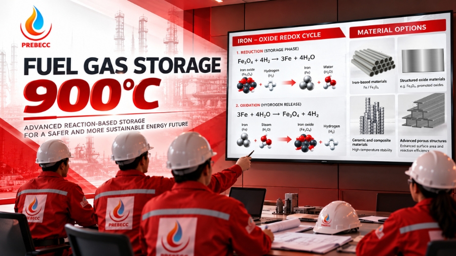
2.2. Reduction of Iron Oxide by Hydrogen
During the charging stage of the cycle, hydrogen reacts with magnetite (Fe₃O₄), an iron oxide, to produce metallic iron and water vapor.
The overall reaction is:
Fe₃O₄ + 4H₂ → 3Fe + 4H₂O
In this reaction, hydrogen acts as a reducing agent. The oxidation states of iron in Fe₃O₄ change as the oxide is reduced to metallic iron. Meanwhile, hydrogen is oxidized and combines with oxygen to form water.
The process involves two simultaneous transformations:
Iron: Fe₃O₄ is reduced to Fe through the gain of electrons.
Hydrogen: H₂ is oxidized to H₂O through the loss of electrons in the overall reaction.
As a result, hydrogen undergoes chemical conversion while the storage material transitions from iron oxide to metallic iron.
In this approach, energy storage and subsequent hydrogen generation depend on the chemical state of the material. System design must therefore account for reaction kinetics, operating temperature, gas supply, heat distribution, and the degree of material conversion.
2.3. Oxidation of Iron by Steam for Hydrogen Release
During the hydrogen release stage, metallic iron reacts with steam to regenerate iron oxide and release hydrogen (H₂).
The overall reaction is:
3Fe + 4H₂O → Fe₃O₄ + 4H₂
In this reaction, metallic iron is oxidized back to Fe₃O₄, while water is reduced to release hydrogen.
The two equations represent the material transformations occurring across the two stages of the cycle:
Stage 1: Hydrogen reduces iron oxide to metallic iron, producing water.
Stage 2: Metallic iron reacts with steam to regenerate iron oxide and release hydrogen.
From an operational perspective, the cycle requires precise control of temperature, gas flow rate, process-gas composition, and the sequence of operating stages. Actual reaction performance also depends on material structure, reactive surface area, diffusion phenomena, and heat-transfer conditions.
Accordingly, the Gas Storage Vessel should be considered an integral component of a thermochemical reaction system rather than merely a conventional gas containment vessel.
2.4. Implications of Materials-Based Storage
The iron–iron oxide cycle enables chemical conversion between hydrogen, steam, and solid materials, creating opportunities to integrate energy storage with high-temperature industrial processes.
Potential benefits include:
- Reducing reliance on maintaining the entire hydrogen inventory as high-pressure compressed gas throughout the energy-storage cycle.
- Supporting the development of cyclic systems for hydrogen storage, transport, and recovery.
- Enabling the use of industrial waste heat where process integration is technically feasible.
- Facilitating modular system designs that integrate the reaction chamber, gas supply equipment, and control systems into functional units.
However, redox-based systems should not automatically be assumed to offer lower costs, easier transportation, or greater safety than conventional storage methods under all conditions. Overall performance depends on active material inventory, heating requirements, reaction rates, cycle efficiency, material regeneration capability, and the specific application.
3. Design Considerations for Gas Storage Vessels Operating at 900°C
3.1. How High Temperatures Affect Material Load-Bearing Performance
Under conventional operating conditions, pressure vessel design focuses on membrane stress, local stress, material strength, and load-bearing capacity at the design pressure.
However, at operating temperatures of up to 900°C, assumptions based on ambient-temperature properties are no longer sufficient to fully assess structural integrity.
At these temperatures, conventional carbon steels and low-alloy steels may experience significant degradation in mechanical properties. Time-dependent deformation, thermal expansion, and interactions between structural components also become critical factors in determining equipment service life.
For a Gas Storage Vessel incorporating a reaction chamber, material selection must account for the actual temperature of each component, applied stresses, operating duration, chemical environment, and heating–cooling cycles.
A material that performs well under short-term loading may not maintain structural stability over tens of thousands of operating hours at elevated temperatures.
Design must therefore extend beyond short-term strength verification to include a comprehensive assessment of long-term service performance.
3.2. Creep Strength and Structural Service Life
Creep is the time-dependent deformation of a material under sustained stress at elevated temperatures, even when the applied stress remains below its instantaneous yield strength.
In equipment operating continuously at 900°C, creep deformation can accumulate throughout the service life. Without appropriate assessment, this may cause dimensional changes, geometric instability, loss of leak tightness, and deterioration of welds or mechanical connections.
Key engineering considerations include:
- Long-Term Allowable Stress Assessment: Determine the material’s load-bearing capacity as a function of temperature and design operating duration. Creep strength data, material properties, and applicable safety factors must be established in accordance with the selected design basis.
- Control of Accumulated Deformation: Evaluate dimensional changes in the vessel shell, transition sections, nozzles, and support components under sustained loading.
- Design Life Assessment: Consider the intended operating duration, transient conditions, and potential degradation of material properties over time.
- Weld and Heat-Affected Zone Assessment: Evaluate how welding procedures, post-weld metallurgical conditions, and stress concentrations affect long-term structural performance.
For PREBECC’s design consultancy project, 900°C is a key design parameter requiring specific assessment of materials and structural integrity. A design operating life, such as 100,000 hours, must be confirmed against the actual project requirements and should not be interpreted as a guaranteed service life.
3.3. Hydrogen–Material Interactions
In addition to temperature, the hydrogen environment is an important consideration when selecting materials for a Gas Storage Vessel.
Hydrogen can diffuse into certain metallic materials and alter their mechanical properties under specific conditions. The extent of these effects depends on material composition, temperature, hydrogen partial pressure, exposure duration, and stress state.
Material selection should therefore not rely solely on tensile strength or yield strength values reported at room temperature.
A comprehensive material assessment should consider:
- Retention of mechanical properties at the design temperature.
- Compatibility with hydrogen and other process media present in the cycle.
- Potential loss of ductility or strength due to environmental interactions.
- Long-term load-bearing capacity and creep resistance.
- Weldability, non-destructive examination requirements, and fabrication quality control.
For systems involving alternating exposure to hydrogen, steam, and iron-based materials, the actual process environment must be assessed at each location. It should not be assumed that all vessel surfaces experience identical gas compositions or temperature conditions.
4. Thermal Fatigue: Challenges Associated with Cyclic Operation
4.1. Combined Pressure and Thermal Loading
During operation, a Gas Storage Vessel may undergo repeated heating, cooling, gas admission, and gas discharge cycles. These operating sequences produce time-varying stresses within the structure.
For the system covered by PREBECC’s design consultancy project, the technical documentation specifies an operating pressure range of 0–11 bar and temperatures varying from ambient conditions up to 900°C. These parameters apply to the system described in the project documentation and are not universal operating limits for all vessels of this type.
Three key mechanisms require evaluation.
Pressure-Induced Fatigue: Pressure fluctuations during charging and discharging cycles generate cyclic stresses in the vessel wall. Nozzles, welds, thickness transitions, and geometric discontinuities may become areas of elevated stress concentration.
Thermal Fatigue: Materials expand and contract as temperatures rise and fall. When different regions of the vessel experience non-uniform temperature changes, restrained thermal expansion can generate additional stresses. Repeated cycling may initiate and propagate fatigue cracks.
Thermomechanical Interaction: Pressure, temperature gradients, mechanical loads, and differences in material properties may act simultaneously on the structure. At sufficiently high temperatures, creep and fatigue can interact, producing damage mechanisms that differ from those associated with either mechanism alone.
4.2. Why Must Operating Cycles Be Evaluated?
A vessel may satisfy static strength requirements yet fail to achieve its intended service life when subjected to repeated thermal and pressure cycles.
The design assessment should therefore establish key operating parameters, including:
- The expected number of charging and discharging cycles over the service life.
- Heating and cooling rates.
- Pressure variation during each cycle.
- Duration of exposure at elevated temperatures.
- Relevant startup, shutdown, and abnormal operating conditions.
These parameters provide the basis for evaluating stress ranges, cumulative fatigue damage, and potential creep–fatigue interaction.
If actual operating conditions differ significantly from the original design assumptions, the service-life assessment should also be reviewed.
5. Double-Wall Design and Finite Element Analysis (FEA)
5.1. Role of the Jacket–Reaction Chamber Configuration
For high-temperature reaction equipment, a double-wall configuration comprising a jacket and an inner reaction chamber may be considered to separate the functions of the internal reaction chamber from those of the external shell.
In this arrangement, the reaction chamber accommodates the thermochemical process, while the outer jacket provides structural support or helps control operating conditions, depending on the specific design configuration.
This approach can facilitate functional separation within the system. However, its effectiveness depends on the detailed configuration, heat-transfer conditions, and mechanical interaction between the two structures.
Key engineering considerations include:
- Temperature differentials between the reaction chamber and the outer shell.
- Differences in the coefficients of thermal expansion of the materials.
- Stresses generated at structural connections between the two walls.
- Load transfer through supports and connecting components.
- Accessibility for inspection, maintenance, and servicing of critical components.
- Leak-tightness under the specified operating conditions and design requirements.
A double-wall design does not inherently eliminate thermal stresses or guarantee safety under all operating conditions. Without proper assessment of the interaction between the two structures, differential thermal expansion may impose additional loads on connections and supports.
5.2. Finite Element Analysis (FEA)
Finite Element Analysis (FEA) is an important engineering tool for assessing the structural integrity of high-temperature equipment, particularly where complex geometries and combined thermal and mechanical loads are involved.
For a Gas Storage Vessel incorporating a reaction chamber operating at temperatures up to 900°C, FEA can be used to evaluate the following:
Temperature Distribution: Simulate temperature fields across the vessel wall, transition regions, and structural connections to identify thermal gradients that may generate significant stresses.
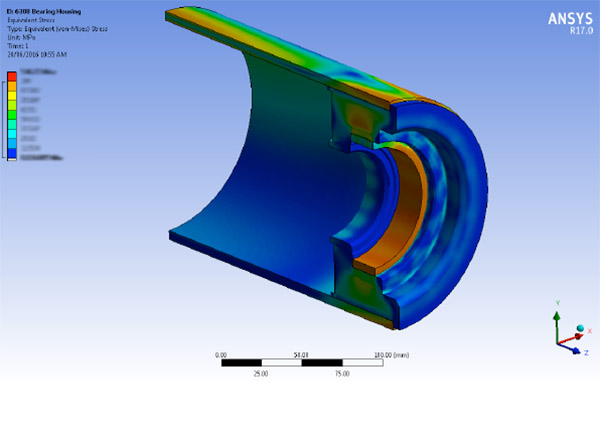
Stress Distribution: Identify areas of elevated stress resulting from internal pressure, thermal expansion, mechanical loads, or interactions between the reaction chamber and outer shell.
Structural Deformation: Evaluate displacements and deformations in the vessel shell, nozzles, connections, and support structures.
Cyclic Operating Conditions: Simulate representative loading scenarios during startup, steady-state operation, cooldown, and transitions between operating stages.
Fatigue and Creep Assessment: Use thermal–mechanical analysis results as inputs for appropriate service-life assessment methods, where supported by the available material data and applicable calculation procedures.
Areas requiring particular attention typically include vessel nozzles, welds, thickness transitions, geometric discontinuities, fixed points, and connections between components with different stiffness characteristics.
However, FEA does not replace verification against the applicable design code. Simulation results are meaningful only when the model, boundary conditions, material data, loading scenarios, and assessment methods are appropriately established. Stress results must also be interpreted against the acceptance criteria defined by the selected design basis.
6. Material Selection and Design Codes for Pressure Equipment
For a Gas Storage Vessel operating at elevated temperatures, material selection must be carried out alongside the establishment of the design basis, operating conditions, and potential failure mechanisms.
6.1. Material Selection Criteria
A comprehensive material selection process should address the following key considerations:
High-Temperature Performance: Verify material properties at the design temperature and assess the ability to maintain structural strength throughout the intended service life.
Creep Resistance: Evaluate creep strength data and other relevant long-term material properties where time-dependent deformation becomes significant at elevated temperatures.
Environmental Compatibility: Assess the effects of hydrogen, steam, and other process media on mechanical properties, material strength, and resistance to degradation.
Fabrication and Weldability: Consider welding procedures, post-weld heat treatment where required, non-destructive examination (NDE), and quality control at critical locations.
Cyclic Load Resistance: Evaluate changes in material performance under repeated thermal, pressure, and mechanical loading.
Material selection should not be based solely on steel grade designations or room-temperature strength values. All relevant properties must be verified against material data applicable to the specific design conditions.
6.2. Design Codes and Compliance Requirements
For industrial pressure equipment projects, the design basis should be established at an early stage to ensure consistency in calculation methods, material requirements, fabrication controls, and conformity assessment documentation.
Depending on the project scope and target market, applicable design frameworks may include EN 13445 for unfired pressure vessels and the Pressure Equipment Directive 2014/68/EU (PED) for pressure equipment falling within its scope in the European Union.
Code selection must reflect the equipment scope, risk classification, design conditions, and applicable regulatory requirements. A conventional pressure vessel code should not automatically be assumed to address all creep, thermal fatigue, or chemical interaction issues associated with operation at 900°C.
For components exposed to extremely high temperatures, the applicability of the selected code, permitted material data, temperature limits, and service-life assessment methods must be verified. Where potential failure mechanisms are not adequately addressed by standard design methods, additional engineering analyses and supporting technical evidence may be required.
This approach helps ensure that a Gas Storage Vessel is not only designed to withstand the specified pressure conditions but also supported by a sound engineering basis for long-term operation.
7. Operational Safety: Chemical Storage Does Not Guarantee Explosion-Proof Performance
Using materials that participate in redox reactions can change how hydrogen is stored and released. However, this technology does not eliminate all hazards associated with flammable gases.
Hydrogen can form flammable mixtures with air if a leak occurs and suitable conditions are present. High-temperature steam also presents a serious burn hazard, while pressure-containing systems remain susceptible to failure if inadequately designed, fabricated, or operated.
Accordingly, the concept of a Gas Storage Vessel designed for fire and explosion risk mitigation should be understood in terms of engineered safety measures, hazard control, and management of reaction conditions—not as an inherent guarantee of explosion-proof performance.
Safety assessments should be based on the actual system configuration and address the following:
- Hydrogen leakage prevention and control at connections and interfaces.
- Assessment of flammable mixture formation in the installation area.
- Control of temperature, pressure, and operating-cycle transitions.
- Ventilation, gas detection, and appropriate protective measures.
- Assessment of abnormal conditions, including heat-source failure, loss of flow, and control-system deviations.
- Requirements for instrumentation, pressure relief devices, and protective systems in accordance with the design basis.
Specific safeguards must be established through risk assessment and applicable standards. Explosion-proof performance cannot be established solely from the chemical reaction mechanism, operating pressure, or double-wall configuration.
8. PREBECC – Engineering Design Consultancy for Demanding Industrial Operating Conditions
For industrial equipment combining elevated temperatures, pressure loading, and chemical reactions, design quality depends on integrating multiple engineering disciplines within a consistent calculation framework.
PREBECC’s recent design consultancy project, involving temperatures of up to 900°C, requires concurrent consideration of creep resistance, thermal fatigue, material compatibility, and structural interaction between the reaction chamber and outer shell.
The engineering challenge extends beyond determining vessel wall thickness. It also involves understanding the loading conditions throughout the operating cycle and evaluating mechanisms that may compromise structural integrity over time.
Key engineering activities include:
Design Condition Assessment: Establish pressure, temperature, process environment, mechanical loads, and operating cycles to define an appropriate design basis.
Material Assessment: Evaluate high-temperature mechanical properties, creep resistance, fatigue strength, and the effects of hydrogen exposure.
Structural Optimization: Assess the reaction chamber and outer shell configuration, with particular attention to connections and regions exposed to significant temperature differentials.
Thermomechanical Simulation: Apply FEA to support the evaluation of temperature distribution, stress, deformation, and potential stress concentrations.
Service-Life Assessment: Evaluate cumulative creep damage, fatigue damage, and combined thermomechanical loading in accordance with the selected design basis.
As PREBECC continues to develop its engineering consultancy capabilities for pressure equipment and industrial systems, the company emphasizes a design approach grounded in actual operating conditions, material data, and appropriate engineering analysis methods.
For thermochemical reaction systems, this approach provides a technical foundation for translating process requirements into structurally sound designs that can be assessed and verified within the defined project scope.
9. Conclusion
Advances in materials-based energy storage technologies are expanding the available approaches to hydrogen storage and release. The iron–iron oxide redox cycle demonstrates how chemical reactions can enable conversion between material states and hydrogen gas under controlled operating conditions.
However, implementing this mechanism in industrial applications requires an integrated design approach addressing heat transfer, material strength, pressure loading, thermal fatigue, and long-term structural performance.
At temperatures of up to 900°C, creep resistance, thermomechanical interactions, and the ability to maintain leak tightness become essential considerations in the engineering design process.
For PREBECC, integrating chemical reaction principles with structural analysis provides a technical foundation for developing design consultancy solutions tailored to industrial systems operating under demanding conditions.
PREBECC – Engineering Expertise in Industrial Equipment Design, Focused on Structural Integrity and Long-Term Operational Reliability.