


The quality of a heat exchanger is not determined by any single manufacturing step. Instead, it is the result of a comprehensive fabrication process that begins with material selection and extends through machining, welding, heat treatment, inspection, and final testing.
Even a minor dimensional deviation or fabrication defect can compromise thermal performance, lead to process fluid leakage, or reduce the long-term reliability and service life of the equipment.
The following are some of the most critical aspects that require close control throughout the manufacturing process.
1. Material Control and Shell Dimensional Accuracy
The shell serves as the primary pressure boundary of a shell-and-tube heat exchanger while enclosing and supporting the tube bundle. In addition to selecting materials that comply with the design specifications and applicable ASME requirements, maintaining tight dimensional tolerances throughout shell fabrication is equally critical.
After the shell plate is cut and rolled into a cylindrical section, the longitudinal seam is welded in accordance with qualified welding procedures. Throughout this stage, maintaining the shell’s roundness is one of the most important quality control requirements.
One of the most critical fabrication defects is excessive shell ovality.
If the shell becomes distorted during fabrication, the outer edges of the baffle plates may interfere with the shell’s internal surface during tube bundle insertion. This interference can cause severe scratching of the shell interior, create potential corrosion initiation sites, or even prevent the tube bundle from being installed altogether.
To minimize distortion, roundness reinforcing rings are installed during the plate rolling and fit-up stages to maintain the shell geometry throughout welding. For large-diameter shells or shells with relatively thin wall thicknesses, these temporary reinforcing rings must provide sufficient rigidity to resist welding-induced deformation.
In addition, temporary end plates are commonly installed before welding to restrain weld shrinkage and improve dimensional stability.
Upon completion of fabrication, shell roundness is verified using dedicated measuring devices or inspection gauges that simulate the tube bundle envelope, ensuring smooth bundle installation without mechanical interference during final assembly.
2. Accurate Nozzle Positioning and Installation
Nozzles provide the inlet and outlet connections for the process fluids flowing through the heat exchanger. Their locations and orientations directly affect field installation and piping alignment.
Before any opening is cut into the shell, the nozzle location must be marked in accordance with the approved Orientation Drawing, followed by inspection and release by the Quality Control (QC) department prior to cutting.
During nozzle fit-up and welding, particular attention should be given to:
- The nozzle projection relative to the equipment centerline.
- The nozzle orientation angle with respect to the connecting flange, verified through dimensional measurement and geometric calculations.
- The flatness of the flange face and the dimensional tolerance between adjacent nozzles, particularly for stacked heat exchanger configurations, where accurate flange alignment is essential for successful field installation.
Proper nozzle positioning not only facilitates piping installation but also minimizes field rework and reduces unnecessary stresses imposed on the connected piping system during operation.
3. Tube Bundle Fabrication and Assembly
The tube bundle is the core component of a shell-and-tube heat exchanger, where heat is transferred between the shell-side and tube-side process fluids.
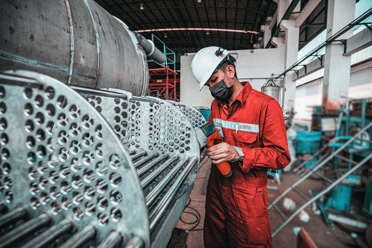
A typical tube bundle consists of the tube sheet, heat transfer tubes, baffle plates, tie rods, spacer tubes, and other structural components that support and maintain the integrity of the assembly.
Among these components, the baffle plates perform two essential functions. They direct the shell-side fluid across the tube bundle to promote turbulence, thereby improving heat transfer efficiency, while also providing mechanical support to the tubes to minimize vibration and tube deflection during operation.
The spacing and configuration of the baffles are carefully engineered to achieve an optimal balance between thermal performance and pressure drop.
4. Baffle Plate Fabrication and Tube Bundle Assembly
4.1. Precision Fabrication of Baffle Plates
Baffle plates are critical components of a shell-and-tube heat exchanger. Their primary function is to direct the shell-side fluid across the tube bundle in a controlled flow pattern, creating turbulence that increases the heat transfer coefficient while optimizing flow velocity and residence time. In addition, they provide mechanical support for the tubes, minimizing vibration and preventing tube deflection during operation.
To achieve these functions, baffle plates must be manufactured with a high degree of dimensional accuracy.
Hole Layout and Drilling
Baffle plate blanks are first cut to the required profile before being temporarily stacked and tack-welded into a single assembly for simultaneous machining. Tube holes are typically produced through a multi-stage drilling process, beginning with pilot drilling for accurate positioning, followed by finish drilling to achieve the specified hole diameter and location.
Precision Machining
For applications requiring minimal clearance between the tubes and baffle holes to reduce shell-side bypass flow, the holes are finish-machined using reamers to achieve tight dimensional tolerances. The stacked baffle assembly is then machined to its final outside diameter, while edges and hole entrances are accurately finished to ensure dimensional consistency throughout the entire bundle.
Baffle Window Machining
Once machining is completed, the individual baffle plates are separated and the baffle windows are cut according to the specified baffle cut percentage (typically 25% or 30% of the shell inside diameter, depending on the thermal and hydraulic design). All cut edges and tube holes are carefully deburred and chamfered to eliminate sharp edges that could damage the tubes during assembly.
4.2. Tube Bundle Assembly and Tube Insertion
The tube bundle is assembled by joining the tube sheets, baffle plates, spacer tubes, and tie rods into a rigid structural framework capable of maintaining dimensional stability throughout fabrication, transportation, and operation.
To facilitate smooth insertion of the completed tube bundle into the shell, sliding shoes are installed along the bottom of the assembly. These components support the bundle during installation while protecting both the shell’s internal surface and the baffle plates from mechanical damage.
Prior to tube insertion, each heat transfer tube is thoroughly cleaned and polished to remove surface oxidation, contaminants, and burrs that could affect the quality of the subsequent tube-to-tubesheet joint.
To improve assembly efficiency and protect the tube ends during installation, manufacturers commonly use a tube insertion guide (bullet) fitted to the leading end of each tube. This temporary guiding tool helps the tube pass smoothly through multiple baffle plates, minimizing the risk of tube-end deformation or surface damage while significantly improving assembly productivity.
5. Tube-to-Tubesheet Joint Fabrication
The tube-to-tubesheet joint is one of the most critical areas of a shell-and-tube heat exchanger. Throughout its service life, this joint is subjected to internal pressure, thermal loading, and differential thermal expansion between the tubes and the tubesheet. If not properly manufactured, it also represents the location most susceptible to leakage.
5.1. Tube-to-Tubesheet Joining Methods
Depending on the design requirements and operating conditions, tube-to-tubesheet joints may be fabricated using one or a combination of the following methods:
- Mechanical tube rolling (tube expanding)
- Seal welding
- Strength welding
- A combination of tube rolling and welding
Mechanical tube rolling creates a tight mechanical joint by plastically expanding the tube against the tubesheet hole. For heat exchangers operating under high pressure, elevated temperatures, or severe process conditions, a combination of welding and tube rolling is commonly adopted to improve joint strength while ensuring long-term leak tightness.
5.2. Tube Rolling Equipment and Quality Control Considerations
Tube rolling is typically performed using either hydraulic tube expanders or mechanical tube expanders, depending on the production requirements and exchanger configuration.
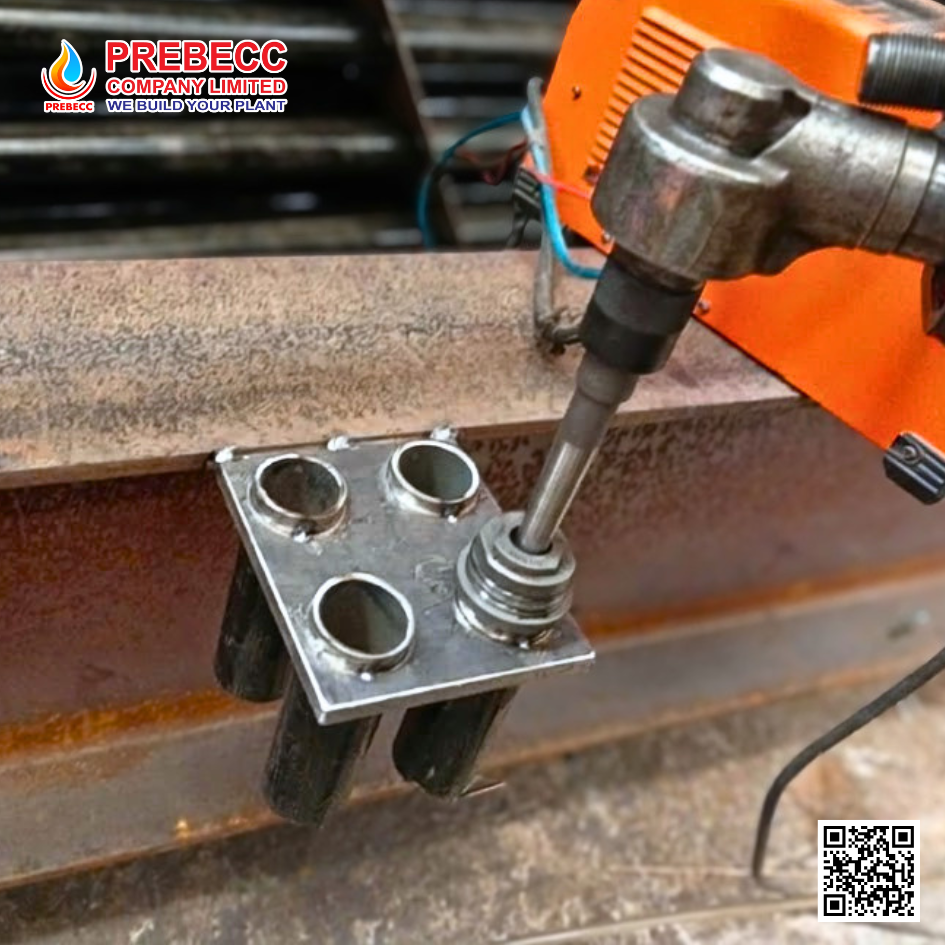
Hydraulic expanders provide uniform expansion forces and high productivity, making them particularly suitable for large heat exchangers with a high tube count. Mechanical expanders, driven by electric or pneumatic motors, are widely used for general fabrication and are typically equipped with tube rolling controllers to maintain consistent expansion torque throughout the rolling process.
To ensure a reliable tube-to-tubesheet joint, several operating practices should be carefully observed:
Proper lubrication of the mandrel and rollers using a dedicated tube rolling lubricant is essential to minimize friction, reduce heat generation, and prevent the expander from seizing inside the tube.
Accurate alignment between the expander mandrel and the tube axis must be maintained throughout the operation. Even slight misalignment can score the tube’s internal surface, accelerate tool wear, and compromise the integrity of the tube-to-tubesheet joint.
Upon completion of tube rolling, the tubesheet should be inspected for dimensional stability using appropriate measuring instruments. Particular attention should be paid to surface flatness and distortion, ensuring that the maximum permissible deformation does not exceed 0.002 × D, with an absolute maximum limit of 5 mm, where D is the outside diameter of the tubesheet.
6. Welding Distortion Control and Post Weld Heat Treatment (PWHT)
Major pressure-retaining components, including the shell, channel, tubesheet, and flanges, are susceptible to the development of residual stresses during welding.
If these stresses are not properly controlled, they may cause distortion of sealing surfaces, dimensional inaccuracies, or premature degradation of the equipment during service.
For pressure components with substantial wall thicknesses, or where specified by the applicable design code, Post Weld Heat Treatment (PWHT) is performed to relieve residual stresses and restore the metallurgical properties of the welded components.
Following PWHT, critical sealing surfaces—such as flange facing and pass partition sealing faces—are typically finish-machined to restore flatness, dimensional accuracy, and sealing integrity prior to final assembly.
7. Heat Exchanger Quality Control Through Non-Destructive Examination (NDE)
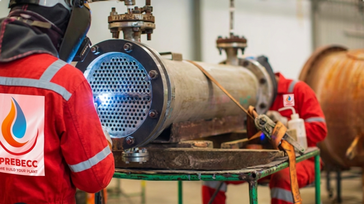
Quality assurance for a heat exchanger is not limited to final inspection; it is integrated throughout every stage of the manufacturing process to ensure compliance with design specifications and applicable industry standards.
Depending on the project requirements and governing codes, inspection and testing activities may include:
- Visual Testing (VT)
- Dimensional Inspection
- Liquid Penetrant Testing (PT)
- Magnetic Particle Testing (MT)
- Ultrasonic Testing (UT)
- Radiographic Testing (RT)
- Leak Testing
- Hydrostatic Testing
The combination of these Non-Destructive Examination (NDE) methods enables manufacturers to identify weld discontinuities, dimensional deviations, and other potential defects before the equipment is released for delivery, ensuring its structural integrity, pressure containment capability, and long-term operational reliability.
8. Compliance with International Standards and Quality Management Systems
The performance and reliability of a shell-and-tube heat exchanger depend not only on manufacturing expertise but also on strict compliance with internationally recognized design, fabrication, inspection, and testing standards.
To ensure consistent product quality and regulatory compliance, manufacturers typically implement the following industry standards throughout the manufacturing process:
- ASME Boiler and Pressure Vessel Code (BPVC), Section VIII for the design and fabrication of pressure vessels.
- TEMA (Tubular Exchanger Manufacturers Association) Standards for the design, fabrication, inspection, and mechanical requirements of shell-and-tube heat exchangers.
- API Standard 660 for shell-and-tube heat exchangers used in petroleum, petrochemical, and natural gas processing industries.
Compliance with these internationally recognized standards establishes a consistent quality framework throughout manufacturing, ensuring dimensional accuracy, structural integrity, pressure containment, and long-term operational reliability. More importantly, it enables heat exchangers to satisfy the stringent technical and quality requirements of industrial projects across domestic and international markets.